
Turn-milling combined machining center

A compound machining center, turning and milling technology, applied in the direction of metal processing equipment, metal processing machinery parts, manufacturing tools, etc., can solve the problems of slow production speed and low efficiency, meet production needs, reduce production costs, and reduce process steps Effect

Active Publication Date: 2022-07-29
FOSHAN NANHAI FUDA PRECISION MACHINERY
View PDF5 Cites 1 Cited by
  • Summary
  • Abstract
  • Description
  • Claims
  • Application Information

AI Technical Summary

Problems solved by technology

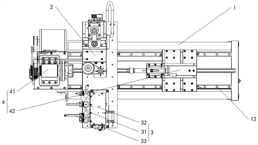
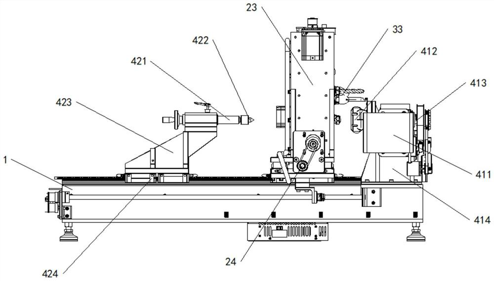
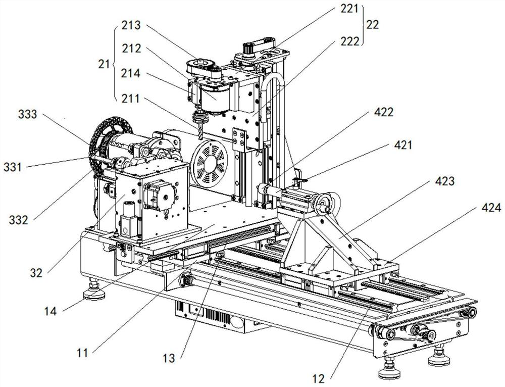
[0004] Based on this, in order to solve the problem that the production speed is slow and the effect is low when the turning and milling processes are carried out separately, the invention provides a kind of turning and milling compound machining center, and its specific technical scheme is as follows:

Method used


Image

  • Turn-milling combined machining center
  • Turn-milling combined machining center
  • Turn-milling combined machining center

Examples


Embodiment Construction

[0025] In order to make the objectives, technical solutions and advantages of the present invention clearer, the present invention will be further described in detail below with reference to its embodiments. It should be understood that the specific embodiments described herein are only used to explain the present invention, and do not limit the protection scope of the present invention.

[0026] It should be noted that when an element is referred to as being "fixed to" another element, it can be directly on the other element or intervening elements may also be present. When an element is referred to as being "connected" to another element, it can be directly connected to the other element or intervening elements may also be present. The terms "vertical", "horizontal", "left", "right" and similar expressions used herein are for the purpose of illustration only and do not represent the only embodiment.

[0027] Unless otherwise defined, all technical and scientific terms used ...


PUM


Abstract

The invention provides a turning and milling combined machining center, which relates to the technical field of machining equipment and comprises a workbench, a turning mechanism and a milling mechanism, a mounting base and a clamping mechanism used for clamping a workpiece to the position above the mounting base are mounted on the workbench. The turning mechanism comprises a turning assembly, a sliding piece and a supporting frame installed on the installation base, the sliding piece is in sliding connection with the supporting frame, the turning assembly is installed on the sliding piece, the turning assembly comprises a turning tool located above the workpiece, and the turning tool can rotate relative to the supporting frame; the milling mechanism comprises a rotating disc, a mounting shell and a plurality of milling assemblies inserted into the rotating disc, the mounting shell is mounted on the mounting seat, the rotating disc is rotatably connected with the mounting shell, the plurality of milling assemblies are separately arranged in the circumferential direction of the rotating disc at intervals, each milling assembly comprises a milling cutter, and the milling cutters can rotate relative to the mounting shell. The problems that the production speed is low and the efficiency is low when turning and milling procedures are carried out separately are solved, and the method has the advantages of being convenient to operate and high in production efficiency.

Description

technical field [0001] The invention relates to the technical field of processing equipment, in particular to a turning-milling compound machining center. Background technique [0002] A milling machine refers to a machine tool that mainly uses a milling cutter to process various surfaces on a workpiece. Usually the rotary motion of the milling cutter is the main motion, and the movement of the workpiece and the milling cutter is the feed motion. It can process planes, grooves, and various curved surfaces, gears, etc. A milling machine is a machine tool that uses a milling cutter to mill a workpiece. A lathe is a machine tool that mainly uses a turning tool to turn a rotating workpiece. On the lathe, drills, reamers, reamers, taps, dies and knurling tools can also be used for corresponding processing. [0003] Traditional milling machines and lathes are single units. When dealing with complex workpieces that require turning and milling processes, the processing plant mus...

Claims


Application Information

Patent Timeline
Patent Type & Authority Applications(China)
IPC IPC(8): B23P23/02B23Q3/06
CPCB23P23/02B23Q3/06Y02P70/10
Inventor 郑成法王志贤
Owner FOSHAN NANHAI FUDA PRECISION MACHINERY
Learn More