Automatic following auxiliary walking rehabilitation wheel type mobile robot device

A technology for mobile robots and assisted walking, applied in the field of rehabilitation robots, can solve the problems that the device cannot play an auxiliary role, and achieve the effect of preventing mutual infection

Inactive Publication Date: 2022-07-29
HEFEI UNIV
View PDF1 Cites 2 Cited by
  • Summary
  • Abstract
  • Description
  • Claims
  • Application Information

AI Technical Summary

Problems solved by technology

[0004] In the current existing technology, most of the rehabilitation training auxiliary devices can only assist the patient to perform preliminary walking. However, some patients need to carry out weight-bearing training for the lower limbs in the middle and late stages of rehabilitation training. At this time, the devices in the prior art cannot play a role. Auxiliary effect; for this reason, the present invention provides a kind of automatic following auxiliary walking rehabilitation wheeled mobile robot device

Method used


Image

  • Automatic following auxiliary walking rehabilitation wheel type mobile robot device
  • Automatic following auxiliary walking rehabilitation wheel type mobile robot device
  • Automatic following auxiliary walking rehabilitation wheel type mobile robot device

Examples


Embodiment 1

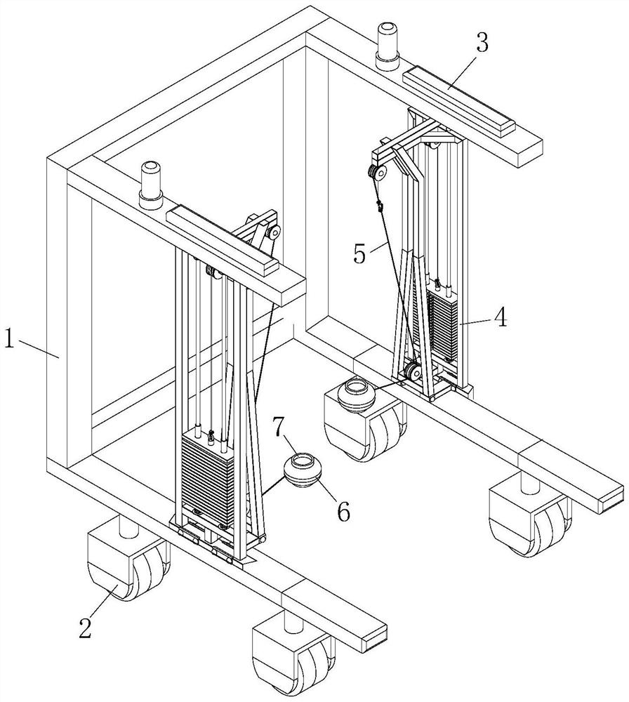
[0028] like figure 1As shown in the figure, an automatic following-assisted walking rehabilitation wheeled mobile robot device according to the embodiment of the present invention includes a walking frame 1, a plurality of sliding wheels 2 are installed at the lower end of the walking frame 1, and two sliding wheels 2 above the walking frame 1 are installed. A support block 3 is installed on both sides, a tensioner assembly 4 is arranged below the support block 3, a traction rope 5 is installed inside the tensioner assembly 4, and an elastic sleeve 6 is installed at one end of the traction rope 5 away from the tensioner assembly 4, and the tensioner The assembly 4 is basically similar to the existing compound wall tensioner, including a counterweight, a plurality of fixed pulleys, a pin and a support guide. Pull the support guide column to move, and then drive the counterweight on the support guide column to move, so as to achieve the effect of weight-bearing training. It shou...

Embodiment 2

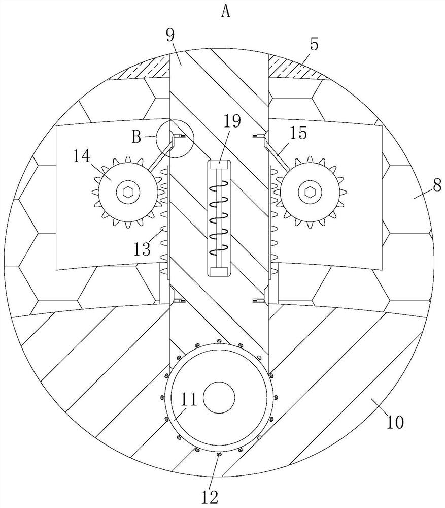
[0038] like Figure 5 As shown in the comparison example 1, another embodiment of the present invention is: an extruding iron block 20 is fixed inside the massage column 9 and located on the side of the electromagnet 19 close to the massage ball 11, and the extruding iron A squeeze spring 21 is fixed between the block 20 and the massage column 9 , a pair of push-pull rods 22 are rotatably connected to the outside of the squeeze iron block 20 , and a squeeze block is rotatably connected to one end of the push-pull rod 22 away from the squeeze iron block 20 23. The squeezing block 23 is slidably connected to the massage column 9, the side of the squeezing block 23 away from the push-pull rod 22 is slidably connected with a liquid storage bag 24, and the liquid storage bag 24 is away from the side of the squeezing block 23. There is a drain pipe that is throughly connected, and the drain pipe is connected to the massage column 9; during operation, when the electromagnet 19 is ene...


PUM


Abstract

The invention belongs to the technical field of rehabilitation robots, and particularly relates to an automatic-following walking-assisting rehabilitation wheel type mobile robot device which comprises a walking frame, a plurality of sliding wheels are installed at the lower end of the walking frame, and the sliding wheels are arranged on the walking frame. Supporting blocks are installed on the two sides of the upper portion of the walking frame, a chest expander assembly is arranged below the supporting blocks, a traction rope is installed in the chest expander assembly, and an elastic sleeve is installed at the end, away from the chest expander assembly, of the traction rope. The elastic sleeves are connected to the legs in a sleeving mode, a patient needs to use leg strength to drive the traction rope to move in the walking process, the traction rope moves to pull a configuration block in the chest expander assembly to move, and therefore the effect that weight training can be conducted on the patient to a certain degree in the rehabilitation training process of the patient is achieved; the patient is helped to recover the free walking ability early.

Description

technical field [0001] The invention belongs to the technical field of rehabilitation robots, in particular to an automatic follow-up auxiliary walking rehabilitation wheeled mobile robot device. Background technique [0002] When some leg diseases or other diseases lead to abnormal lower extremity function of patients, rehabilitation training of lower extremities is often required to help patients recover the ability to walk freely. At present, the rehabilitation training of lower extremities has been proposed to be assisted by devices. [0003] A Chinese patent with publication number CN103932874B discloses a multifunctional lower limb rehabilitation moped, which belongs to the technical field of medical devices, and relates to a power assist device that provides rehabilitation training for people with lower limb walking dysfunction due to illness, including rolling wheels arranged on the chassis The lower part of the frame is fixed on the chassis; a sprocket chain transmi...

Claims


Application Information

Patent Timeline
Patent Type & Authority Applications(China)
IPC IPC(8): A63B23/04A63B21/08A61H3/04A61H39/04A61H15/00
CPCA63B23/04A63B21/08A61H3/04A61H39/04A61H15/00A61H2003/006A61H2003/005A61H2015/0042A61H2205/10A61H2201/1659
Inventor 吴其林
Owner HEFEI UNIV
Why Eureka
Try Eureka