Chronic disease medical care robot based on Internet of Things
A chronic disease and robot technology, applied in the field of chronic disease medical care robots, can solve problems such as breeding bacteria and reduce the difficulty of nursing.
- Summary
- Abstract
- Description
- Claims
- Application Information
AI Technical Summary
Problems solved by technology
Method used
Image
Examples
Embodiment 1
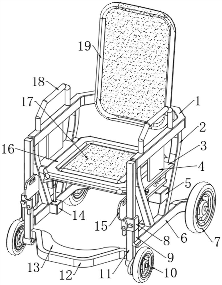
[0034] Refer to the attached Figure 1-9 , A chronic disease medical care robot based on the Internet of Things, including an intelligent host 5, a support tube 1 and two square tubes 6, the support tube 1 is a C-shaped structure, and the two square tubes 6 are arranged in parallel below the support tube 1. The support tube 1 A backboard 19 and two symmetrically arranged handrails 18 are fixedly connected to the wall of the pipe, and two connecting frames 2 are symmetrically and fixedly connected to the lower end of the support pipe 1, and the lower end of the connecting frame 2 is fixed to the pipe wall of the square pipe 6. Connection, a frame 16 is fixedly connected between the two connecting frames 2, and a support mechanism is arranged in the frame 16. The support mechanism is used to cooperate with the frame 16 to form a plane to support the user's body, and the support mechanism is removed from the frame 16. After that, it is used to assist the user to defecate;
[0035]...
Embodiment 2
[0038] Embodiment 2: What is different based on Embodiment 1 is;
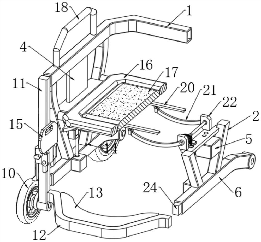
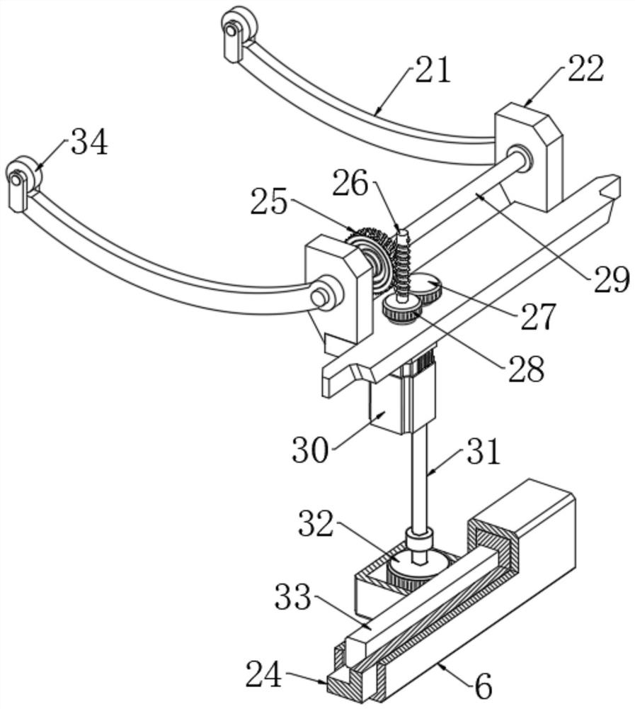
[0039] Refer to the attached Figure 2-4 , the support mechanism includes a transmission shaft 29 and a seat plate 17, the seat plate 17 is located in the frame 16, the lower end side of the frame 16 is hinged with the seat plate 17 through two hinges, and the shaft wall of the transmission shaft 29 is connected with two bearings The seat 22, the two bearing seats 22 are fixedly connected with the connecting frame 2, the two ends of the transmission shaft 29 are fixedly connected with support arms 21, and one end of the support arms 21 extends to the bottom of the seat plate 17, the shaft wall of the transmission shaft 29 A worm wheel 25 is fixedly connected to the upper part, and the worm wheel 25 is engaged with the worm 26;
[0040] The lower end of the seat plate 17 is fixedly connected with two parallelly arranged chutes 20, both of which are provided with pulleys 34, and the two pulleys 34 are respective...
Embodiment 3
[0042] Embodiment 3: The difference based on Embodiment 1 is;
[0043] Refer to the attached figure 2 and Image 6 , the transmission mechanism includes a rotating shaft 31, one end of the rotating shaft 31 is rotatably connected with the upper end of the casing 14 through a second rolling bearing, one end of the rotating shaft 31 extends into the casing 14 and is fixedly connected with the first gear 32, the square tube 6 is provided with teeth The bar 33, the rod wall of the rectangular rod 24 is fixedly connected with the rack 33 through the groove, the tube wall of the square tube 6 is provided with a bar-shaped opening 23, and one side of the first gear 32 passes through the bar-shaped opening 23 and is connected with the rack. 33 meshes, the side wall of the connecting frame 2 is fixedly connected with the motor 30, the output end of the motor 30 is fixedly connected with the second gear 28, the inner core of the second gear 28 has a third gear 27, and the upper end of...
PUM
 Abstract
Description
Claims
Application Information
 - Generate Ideas
- Intellectual Property
- Life Sciences
- Materials
- Tech Scout
- Unparalleled Data Quality
- Higher Quality Content
- 60% Fewer Hallucinations
Browse by: Latest US Patents, China's latest patents, Technical Efficacy Thesaurus, Application Domain, Technology Topic, Popular Technical Reports.
© 2025 PatSnap. All rights reserved.Legal|Privacy policy|Modern Slavery Act Transparency Statement|Sitemap|About US| Contact US: help@patsnap.com


