Rack-mounted environment humidity control device

A technology of environmental humidity and control devices, applied in the direction of humidity control, control/regulation system, non-electric variable control, etc., can solve the problems of occupying too much cabinet rack space, high price, equipment damage, etc., to save space and save cost effect

Pending Publication Date: 2022-07-26
辽宁吉左网络科技有限公司
View PDF0 Cites 2 Cited by
  • Summary
  • Abstract
  • Description
  • Claims
  • Application Information

AI Technical Summary

Problems solved by technology

[0003] However, the emergence of a new concept is often accompanied by some new problems. For example, due to the relatively small space in the cabinet, if the traditional humidifier and dehumidifier are used for humidity control inside the cabinet, not only the price is high and the volume is large, but also due to the use of two humidifiers at the same time. Too much rack space is occupied by different kinds of equipment, often having to give up the precise control of the humidity in the cabinet
Too high or too low humidity often greatly exceeds the humidity tolerance limit of the electronic equipment in the cabinet, which can easily lead to equipment damage

Method used


Image

  • Rack-mounted environment humidity control device
  • Rack-mounted environment humidity control device

Examples


Embodiment 1

[0030] Idle mode: When the humidity inside the cabinet is in the normal range, the relative humidity is generally between 35% and 75%, and the humidity control device is in an idle state. At this time, the air circulation fan 4, the dehumidification unit, and the humidification unit stop running.

Embodiment 2

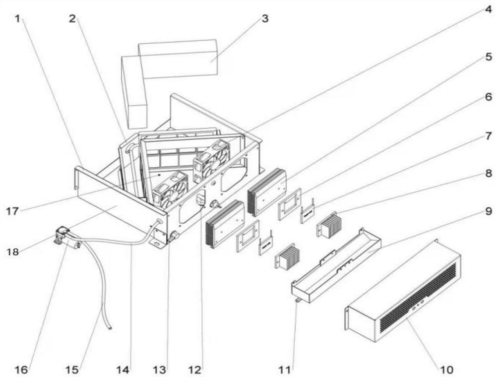
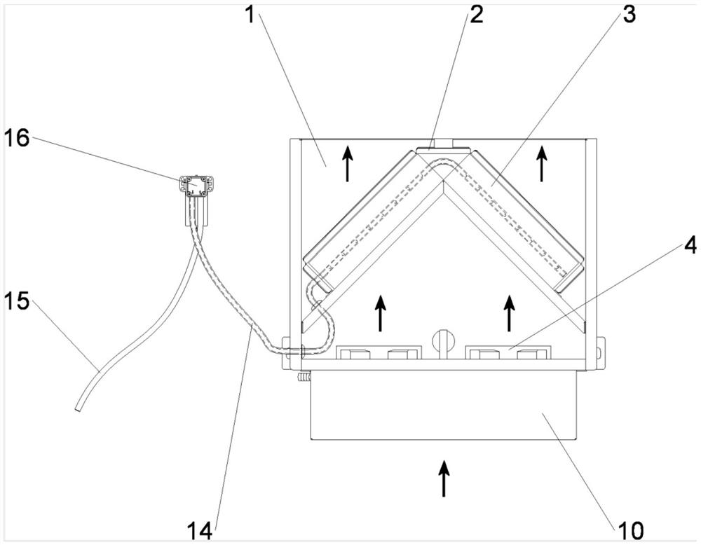
[0032] Humidification mode: when the humidity inside the cabinet is lower than the normal range, the relative humidity is usually lower than 35%, the humidification unit is running, the control unit first starts the humidification feed water pump 16, then the humidification water supply pipe 15 and the humidification water supply pipe 14 feed the humidification water tray structure. A small amount of liquid water is injected into 17, so that the porous humidifying membrane 3 is soaked with water, and the control unit starts the airflow circulation fan 4 to run continuously. The humidity inside the cabinet increases. When the humidity reaches the normal range, the humidification is stopped and the idle mode is entered. The humidification feed water pump 16 operates intermittently, but when the water level in the humidification water tray structure 17 exceeds the warning water level, the humidification water tray water level sensor will 12 is detected, at this time, the central c...

Embodiment 3

[0034] Dehumidification mode: When the internal humidity of the cabinet is higher than the normal range, the relative humidity is usually higher than 75%, the dehumidification unit operates, the control unit first applies DC power to the semiconductor refrigeration sheet 7, and simultaneously starts the air circulation fan 4, and the air flow is driven by the air circulation channel 1. The air inlet 10 enters. At this time, due to the Peltier effect, the condensing surface cooler 8 is cooled and the radiating surface cooler 5 is heated up, and the high-humidity airflow flows through the condensing surface cooler 8. When the temperature is high, the water vapor will condense on the condensing surface cooler 8, form water droplets and fall into the condensed water tank 9. The condensed water collected by the condensed water tank 9 is discharged from the condensate water outlet 11 through the pipeline, and the condensed water is diverted. The plate gap flows into the condensed wat...


PUM


Abstract

The invention discloses a rack-mounted environment humidity control device, and relates to the technical field of modular data center environment control, the rack-mounted environment humidity control device comprises a device body, an airflow circulation unit, a dehumidification unit, a humidification unit and a central control unit, the airflow circulation unit comprises an air inlet, an airflow circulation channel and an airflow circulation fan, an air inlet is formed in the front part of the device body, an airflow outlet is formed in the rear part of the device body, and two airflow circulating fans are mounted on the device body; according to the rack type environment humidity control device, by arranging the airflow circulation unit, the dehumidification unit, the humidification unit and the central control unit, three different working modes can be achieved, so that the cost can be saved, meanwhile, the space occupied by the device is saved, the humidification function and the dehumidification function are combined into one, and the environment humidity control device is convenient to use. Therefore, the device can realize the humidifying and dehumidifying functions.

Description

technical field [0001] The invention relates to the technical field of environmental control of a modular data center, in particular to a rack-type environmental humidity control device. Background technique [0002] At present, the concept and products of modular data center have been deeply rooted in the hearts of the people, and the modular data center with closed hot and cold aisles using cabinets as modules has become an important data center in the history of data center development due to its high efficiency, energy saving, economy and many other advantages. change. [0003] However, the emergence of a new concept is often accompanied by some new problems. For example, due to the relatively small space of the cabinet, if the traditional humidifier and dehumidifier are used for the humidity control inside the cabinet, it is not only expensive and bulky, but also because of the simultaneous use of two Taking up too much cabinet rack space with a variety of different eq...

Claims


Application Information

Patent Timeline
Patent Type & Authority Applications(China)
IPC IPC(8): G05D22/02
CPCG05D22/02
Inventor 马震钟亚呋
Owner 辽宁吉左网络科技有限公司
Why Eureka
Try Eureka