


Quick Research
Generate reliable direction feasibility study reports for your R&D in just a few steps.

Technical Q&A
Discover and master advanced knowledge NOW. Basics, ideas, possibilities, all at once.

Find Solutions
As an expert in R&D theories, this can generate solutions to your technical problems instantly.

Evaluate Feasibility
Analyze your overall solution with one click, know your potential R&D risks in advance.

Monitor Landscape
Get weekly tech updates, stay abreast of the latest tech innovations and key insights.
Electrical automation detection device for power distribution equipment
An electrical automation and detection device technology, applied in the substation/distribution device housing, substation/switchgear cooling/ventilation, electrical components, etc., can solve the problem that the cooling device cannot meet the cooling demand, etc. Effect
- Summary
- Abstract
- Description
- Claims
- Application Information
AI Technical Summary
Problems solved by technology
Method used
Image

Examples
Embodiment 1
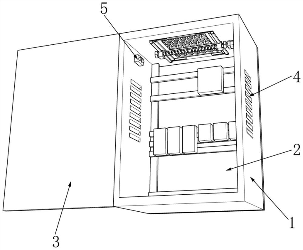
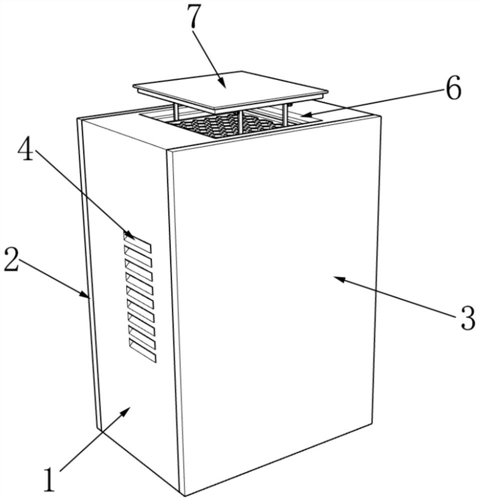
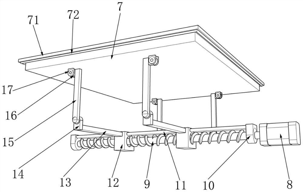
[0023] Example one, by Figure 1-6 Given, the present invention includes a cabinet 1, a maintenance door 2 is detachably installed on the back of the cabinet 1, a switch door 3 is movably installed on the front of the cabinet 1, and cooling holes 4 are opened on the left and right sides of the cabinet 1. A temperature and humidity monitor 5 is fixedly installed on the inner wall of the cabinet body 1, a card slot 6 is opened on the top of the cabinet body 1, a lifting sunshade 7 is clipped inside the card slot 6, and a drive assembly is fixedly installed on the top of the inner cavity of the cabinet body 1. The bottom surface of the lifting sunshade 7 is rotatably connected with the drive assembly, the four sides of the lifting sunshade 7 are fixedly installed with waterproof flanges 71, the bottom of the waterproof flange 71 is fixedly installed with rubber strips 72, and the sides of the lifting sunshade 7 are all connected with the card groove The inner walls of The shaft ...
Embodiment 2
[0024] Example two, by Figure 4-6 As shown, on the basis of the first embodiment, the bottom of the card slot 6 is provided with an installation square groove 18, the inner walls of the left and right sides of the installation square groove 18 are provided with L-shaped guide grooves 19, and the inner walls of the L-shaped guide groove 19 are provided with A slot, a dustproof assembly 20 is movably installed inside the L-shaped guide groove 19, and the dustproof assembly 20 includes a first installation rod 21. The side of the first installation rod 21 is fixedly installed with a flexible plastic plate 22, and the side of the flexible plastic plate 22 A second installation rod 23 is fixedly installed, a dustproof net 24 is fixedly installed in the middle of the dustproof assembly 20 , cylindrical protrusions 25 are fixedly installed on the left and right sides of the first installation rod 21 , and the left and right sides of the second installation rod 23 are fixedly installe...
PUM
 Abstract
Description
Claims
Application Information
 - R&D Engineer
- R&D Manager
- IP Professional
- Industry Leading Data Capabilities
- Powerful AI technology
- Patent DNA Extraction
Browse by: Latest US Patents, China's latest patents, Technical Efficacy Thesaurus, Application Domain, Technology Topic, Popular Technical Reports.
© 2024 PatSnap. All rights reserved.Legal|Privacy policy|Modern Slavery Act Transparency Statement|Sitemap|About US| Contact US: help@patsnap.com