Device and method for testing filtering performance of ventilation system of railway vehicle

A technology for filtering performance testing and ventilation system, which is applied in the field of rail vehicles and can solve problems such as inability to accurately measure the filtering performance of ventilation systems.

Pending Publication Date: 2022-07-22
CRRC QINGDAO SIFANG CO LTD
View PDF0 Cites 2 Cited by
  • Summary
  • Abstract
  • Description
  • Claims
  • Application Information

AI Technical Summary

Problems solved by technology

[0004] The main purpose of the present invention is to provide a device and method for testing the filtration performance of the ventilation system of rail vehicles, so as to solve the problem that the filtration performance of the ventilation system of rail vehicles cannot be accurately measured in the prior art

Method used


Image

  • Device and method for testing filtering performance of ventilation system of railway vehicle
  • Device and method for testing filtering performance of ventilation system of railway vehicle
  • Device and method for testing filtering performance of ventilation system of railway vehicle

Examples


Embodiment 1

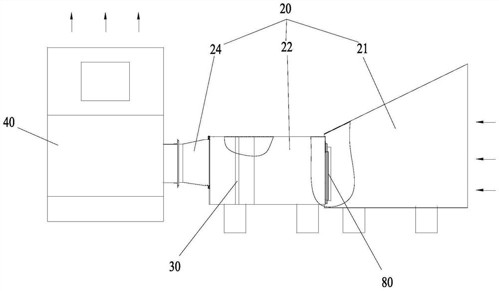
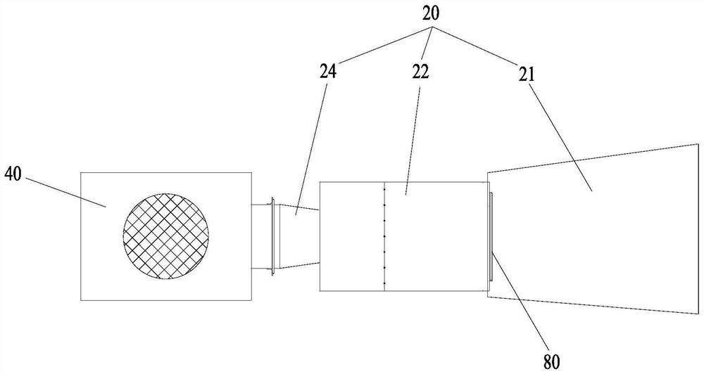
[0048] like Figure 1 to Figure 2 , Figure 9 and Figure 13 As shown, the ventilation system filtration performance testing device for rail vehicles includes a spray assembly 10, a test air duct assembly 20, a first filter 30, a cooling air simulation assembly 40, a wind resistance measurement assembly 60 and a weighing assembly. The spray assembly 10 is used for spraying the material to be filtered. The object to be tested 80 is arranged in the test air duct assembly 20 , and the spray assembly 10 communicates with the test air duct assembly 20 . The first filter 30 is disposed in the test air duct assembly 20 . The cooling air simulating assembly 40 communicates with the test air duct assembly 20 , and the cooling air generated by the cooling air simulating assembly 40 passes through the filter surface of the test piece 80 . The wind resistance measuring assembly 60 is used to measure the air volume and resistance of the DUT 80 . The weighing component is used to weigh...

Embodiment 2

[0075] Compared with the first embodiment, the composition structure of the filter performance testing device for the ventilation system of the rail vehicle is different in this embodiment.

[0076] Specifically, as Figure 5 to Figure 8 As shown, the ventilation system filtration performance testing apparatus for rail vehicles further includes a train wind simulation assembly 50 . The train wind simulation component 50 communicates with the test air duct component 20 , and the wind direction of the train wind generated by the train wind simulation component 50 is parallel to the filter surface of the test piece 80 . That is, the train wind generated by the train wind simulation assembly 50 blows in parallel from the surface of the test piece 80 during the test. The train wind simulation component 50 can simulate the train wind around the object to be tested 80 during the actual operation of the rail vehicle, so that the real wind environment of the object to be tested 80 can...


PUM


Abstract

The invention provides a ventilation system filtering performance testing device and method for a railway vehicle. The ventilation system filtering performance testing device for the railway vehicle comprises a spraying assembly and a testing assembly, wherein the spraying assembly is used for spraying an object to be filtered; the to-be-tested piece is arranged in the test air duct assembly, and the spraying assembly is communicated with the test air duct assembly; the first filter is arranged in the test air duct assembly; the cooling air simulation assembly is communicated with the test air duct assembly, and cooling air generated by the cooling air simulation assembly penetrates through the filtering surface of the to-be-tested piece; the wind resistance measuring assembly is used for measuring the wind volume and the resistance of the to-be-tested piece; the weighing assembly is used for weighing the weight of the to-be-filtered object and the weight of the to-be-tested piece before and after filtering. The problem that the filtering performance of the ventilation system of the railway vehicle cannot be accurately measured in the prior art is solved.

Description

technical field [0001] The present invention relates to the technical field of rail vehicles, and in particular, to a device and method for testing the filtration performance of a ventilation system for rail vehicles. Background technique [0002] In the operation of rail vehicles, especially high-speed EMUs, during the annual floating of willow catkins, the air inlets such as the filter screen of the apron of the equipment cabin and the filter screen of the new air outlet of the air conditioner are seriously blocked, and the workload, labor intensity, etc. It is difficult to clean up, which greatly increases the cost of after-sales, maintenance and operation of the vehicle. The blockage of the filter screen has a great impact on the ventilation performance of the equipment, and the improvement of the performance and structure of the filter screen of the equipment cabin skirt board has become a top priority. However, in the prior art, the device for testing the filtration p...

Claims


Application Information

Patent Timeline
Patent Type & Authority Applications(China)
IPC IPC(8): G01M99/00
CPCG01M99/007
Inventor 雷银霞丁叁叁陈大伟姚拴宝闫中奎王维斌
Owner CRRC QINGDAO SIFANG CO LTD
Why Eureka
Try Eureka