Three-dimensional transient combustion rate measuring device and combustion rate measuring method

A measuring device, three-dimensional transient technology, applied in the direction of measuring fluid velocity using thermal variables, jet propulsion device, rocket engine device, etc., can solve the problems of inability to calculate the distribution of burning rate, low reliability, measurement error, etc., to achieve Excellent transient burning rate measurement effect, high reliability and precision, and accurate measurement results

Pending Publication Date: 2022-07-22
BEIHANG UNIV
View PDF0 Cites 0 Cited by
  • Summary
  • Abstract
  • Description
  • Claims
  • Application Information

AI Technical Summary

Problems solved by technology

However, the reliability of the two schemes is low during use, and the fuse signal is often unable to be identified, which leads to measurement failure
The acoustic emission method can only measure the burning rate under a certain working pressure, and is limited by factors such as the combustion chamber pressure, and the upper limit of the pressure is low; the measurement algorithm of the ultrasonic dynamic method is complicated, the test range is narrow, and it is greatly affected by the environment. It has not been popularized yet; and the commonly used start-stop average method has measurement errors, and cannot calculate the distribution of the burning rate along the axial direction of the solid charge
[0005] That is to say, each solution in the prior art has different disadvantages, how to overcome these disadvantages and achieve a better burning rate measurement effect is a technical problem to be solved in the prior art

Method used


Image

  • Three-dimensional transient combustion rate measuring device and combustion rate measuring method
  • Three-dimensional transient combustion rate measuring device and combustion rate measuring method
  • Three-dimensional transient combustion rate measuring device and combustion rate measuring method

Examples


Embodiment Construction

[0056] In order to make the purposes, technical solutions and advantages of the embodiments of the present invention clearer, the technical solutions in the embodiments of the present invention will be clearly and completely described below with reference to the accompanying drawings in the embodiments of the present invention. Obviously, the described embodiments These are some embodiments of the present invention, but not all embodiments. The components of the embodiments of the invention generally described and illustrated in the drawings herein may be arranged and designed in a variety of different configurations.

[0057] Thus, the following detailed description of the embodiments of the invention provided in the accompanying drawings is not intended to limit the scope of the invention as claimed, but is merely representative of selected embodiments of the invention. Based on the embodiments of the present invention, all other embodiments obtained by those of ordinary skill...


PUM


Abstract

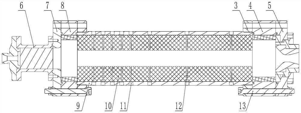
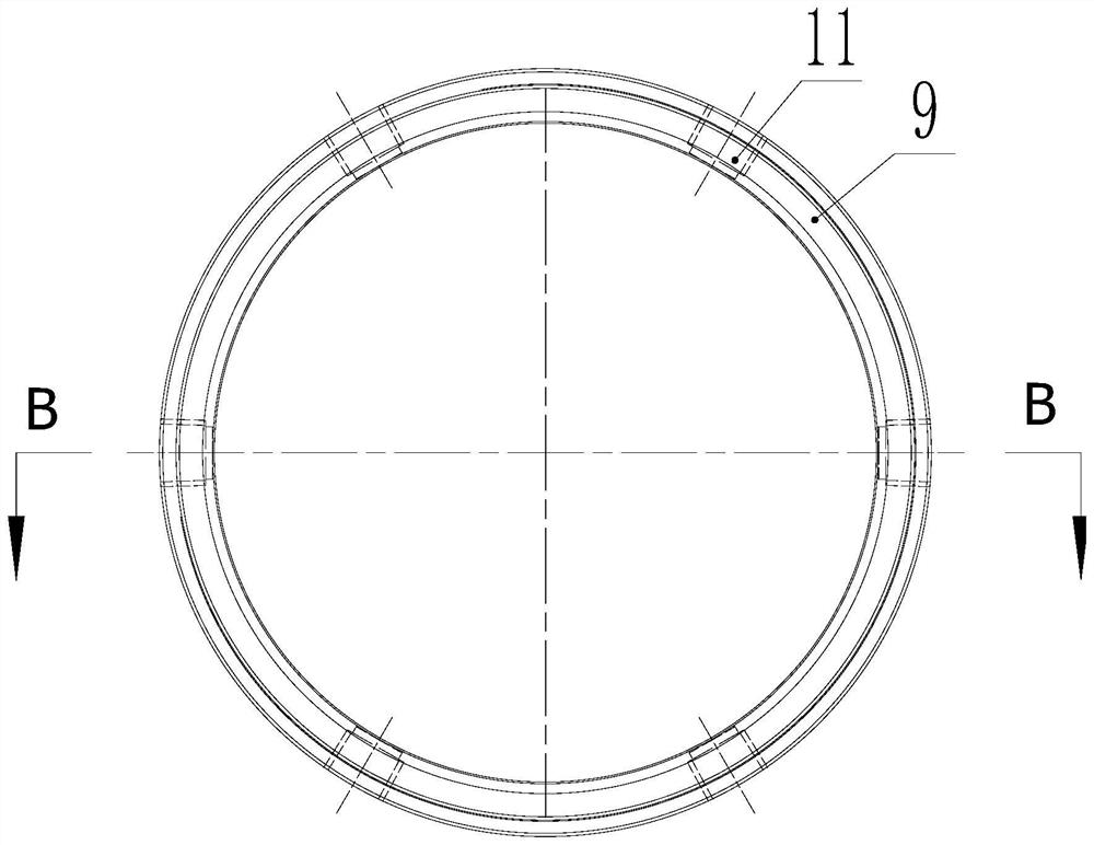
The invention relates to the field of rocket engines, in particular to a three-dimensional transient combustion rate measuring device and a combustion rate measuring method. The three-dimensional transient combustion rate measuring device comprises a shell, a grain and a thermocouple, the grain is a cylinder, a first circular hole matched with the grain is formed in the shell, and the grain is arranged in the first circular hole; the grain is provided with a second circular hole penetrating through the grain; the shell is provided with a first test hole; second test holes are formed in the grain, the first test holes and the second test holes are arranged in a one-to-one correspondence mode, and the thermocouples penetrate through the first test holes and then are inserted into the second test holes; the axis of the first test hole is perpendicular to the axis of the shell. The number of the first test holes is multiple, and the first test holes are arranged on the shell in a matrix mode on an expanded view of the shell. The burning rate measuring method comprises the following steps: selecting a grain and a shell; the grain is installed in the shell; installing a thermocouple; engine hot testing; temperature changes are collected and concluded at all the measuring points, and the burning speed is worked out. According to the invention, multi-dimensional detection is realized, and a better transient combustion rate measurement effect is obtained.

Description

technical field [0001] The invention relates to the field of rocket engines, in particular to a burning rate measurement method of a three-dimensional transient burning rate measuring device. Background technique [0002] The solid-liquid rocket engine is a chemical rocket engine that generally uses a liquid oxidant and a solid fuel. The liquid oxidant is injected into the combustion chamber and mixed with the solid fuel for combustion. The grain is thermally decomposed and the oxidant is further burned to release heat. The nozzle accelerates the ejection to generate thrust. The flow of liquid oxidant can usually be precisely controlled by the venturi, so the burning rate of solid fuel will be the key to the study of solid-liquid rocket motor. [0003] The burning rate of solid fuel in a solid-liquid rocket motor is an important indicator to characterize the working performance of the engine, which is closely related to the propellant formula and the flow rate of the oxidan...

Claims


Application Information

Patent Timeline
Patent Type & Authority Applications(China)
IPC IPC(8): F02K9/96F02K9/10F02K9/34G01P5/10
CPCF02K9/96F02K9/10F02K9/34F02K9/343G01P5/10
Inventor 蔡国飙魏天放田辉陈瑞凯卢裕东姜宪珠
Owner BEIHANG UNIV
Why Eureka
Try Eureka