Automobile steering gear pressing block and steering gear

A technology of automobile steering gear and steering gear, which is applied in the direction of mechanical steering gear, etc. It can solve the problems of limited buffer capacity, extra cost and man-hours, and gaps that cannot be adjusted, so as to save costs, avoid failure risks, and save assembly man-hours.

Pending Publication Date: 2022-07-22
ZHEJIANG GEELY HOLDING (GROUP) CO LTD +1
View PDF0 Cites 0 Cited by
  • Summary
  • Abstract
  • Description
  • Claims
  • Application Information

AI Technical Summary

Problems solved by technology

[0003] In the existing scheme, O-rings are arranged on the circumference of the briquetting block and the end face of the briquetting plug to buffer the abnormal noise generated by the collision between the briquetting block and the shell during the movement, but there are the following defects: the interference of the O-ring is only About 0.5mm, it is too large to be assembled, so the cushioning capacity is limited. When the force is large, the metal collision between the pressing block and the shell may still occur, resulting in noise; Attenuation, permanent deformation, depression to the surface of the briquetting block, and the buffering and damping effect will fail; when the O-ring is pressed in with interference, it is prone to distortion and there is a risk of cutting, resulting in the failure of the buffering effect; if it is stuck in the shell wall, the gap cannot adjustment; and the O-ring is assembled to the pressure block, requiring additional cost and man-hours

Method used


Image

  • Automobile steering gear pressing block and steering gear
  • Automobile steering gear pressing block and steering gear
  • Automobile steering gear pressing block and steering gear

Examples


Embodiment Construction

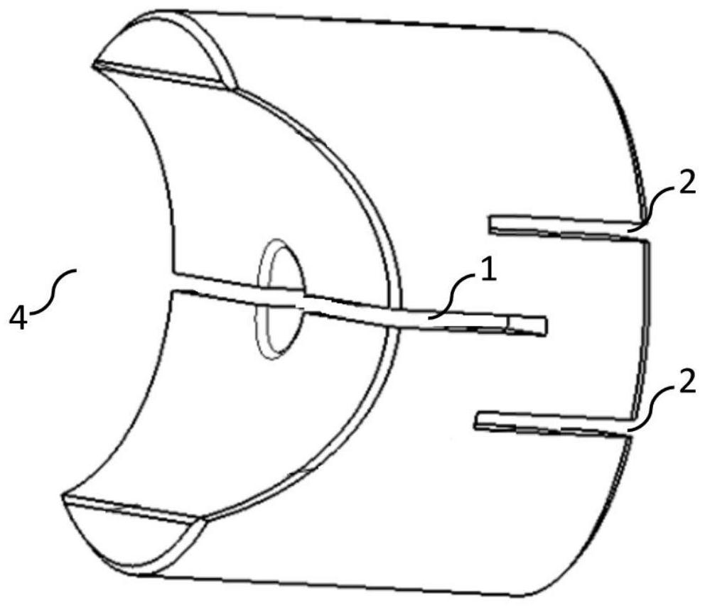
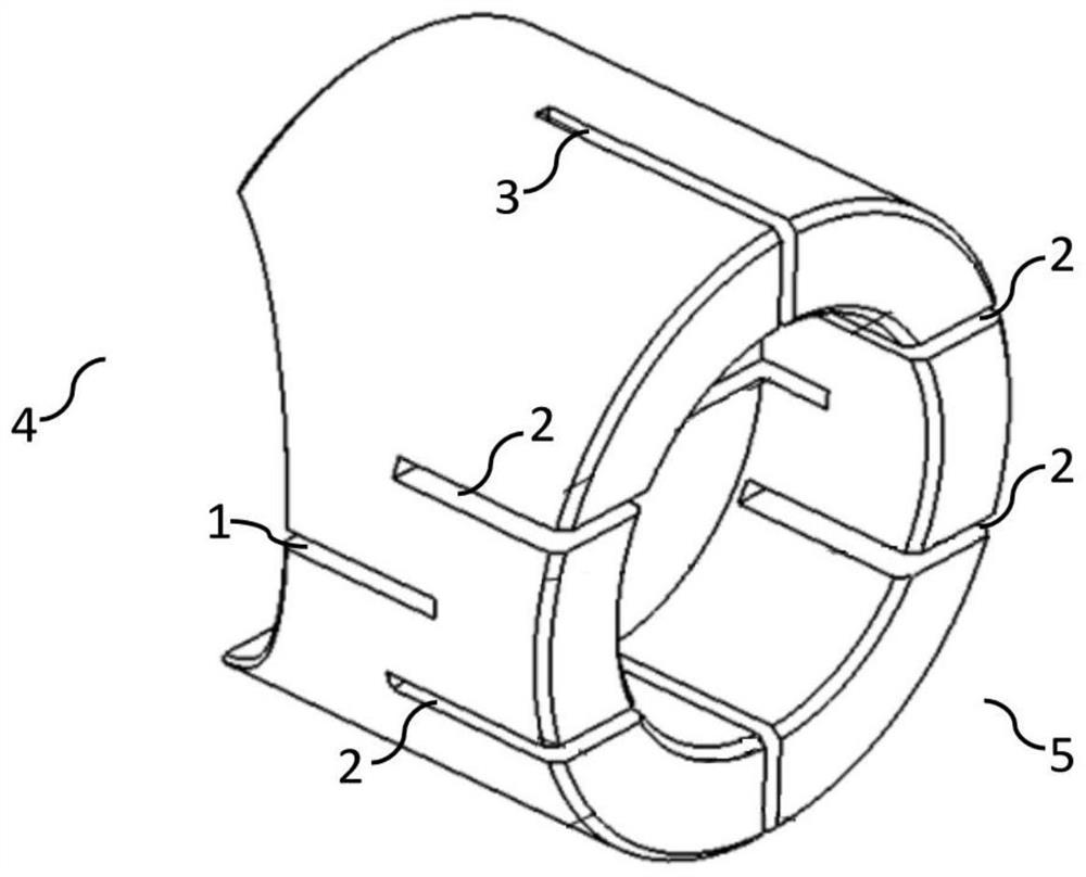
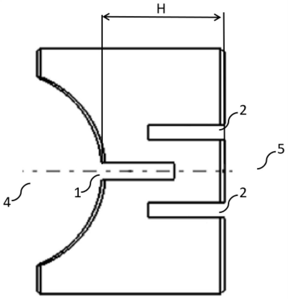
[0028] figure 1 It is a schematic diagram of a three-dimensional structure according to an embodiment of the present invention. figure 2 It is a schematic three-dimensional structure diagram from another perspective according to an embodiment of the present invention. In one embodiment, as figure 1 and figure 2 As shown, the pressure block of the automobile steering gear includes a pressure block body, and the pressure block body is cylindrical and has a first end 4 and a second end 5 arranged oppositely, and the first end 4 is an inner part matched with the steering gear rack. Concave arc surface, in addition, at least one first groove 1 is provided on the pressing block body, which traverses the inner concave arc surface and extends in the depth direction toward the second end 5; and the second end 5 is provided with multiple The second grooves 2 are spaced apart, and the second grooves 2 are equally spaced on both sides of the first groove 1 , and the depth direction o...


PUM


Abstract

The invention provides an automobile steering device pressing block, and belongs to the technical field of steering device accessories. Comprising a pressing block body, the pressing block body is cylindrical and is provided with a first end and a second end which are oppositely arranged, the first end is an inwards-concave cambered surface matched with a steering gear rack, the pressing block body is provided with at least one first groove transversely penetrating through the inwards-concave cambered surface, and the depth direction of the first groove extends towards the direction of the second end; the second grooves are formed in the second end at intervals, the second grooves are distributed in the two sides of the first groove at equal intervals, and the depth directions of the second grooves extend towards the direction of the first end. The first groove and the second grooves formed in the second end at intervals are formed in the pressing block, the second grooves are distributed in the two sides of the first groove at equal intervals, the depth direction of the second grooves extends towards the first end, and the first groove and the second grooves are matched with each other to replace an O-shaped ring; therefore, the cost and the assembly working hours are saved, and the risk of assembly cut failure can be avoided.

Description

technical field [0001] The invention relates to the technical field of steering gear accessories, in particular to an automobile steering gear pressing block. Background technique [0002] A small gap is set between the pressure block and the pressure block plug, and the buffer spring is used to complete the small axial movement perpendicular to the rack to realize the smooth rotation of the rack. However, during the movement of the rack, due to the lateral force, the pressure block and the shell collide to produce abnormal noise. The ring has an interference fit with the shell, which is used to buffer and reduce abnormal collision noise. [0003] In the existing solution, O-rings are arranged in the circumferential direction of the pressure block and on the end face of the pressure block plug to buffer the abnormal noise caused by the collision between the pressure block and the shell during the movement, but there are the following defects: the interference of the O-ring ...

Claims


Application Information

Patent Timeline
Patent Type & Authority Applications(China)
IPC IPC(8): B62D3/12
CPCB62D3/12B62D3/126
Inventor 田思秀王华李军营夏金龙
Owner ZHEJIANG GEELY HOLDING (GROUP) CO LTD
Why Eureka
Try Eureka