Auxiliary device for balance shaft

An auxiliary device and balance shaft technology, which is applied in the direction of balance weight, spring/shock absorber, vibration suppression adjustment, etc., can solve problems such as noise and instantaneous force

Inactive Publication Date: 2017-03-01
KYMCO
View PDF6 Cites 0 Cited by
  • Summary
  • Abstract
  • Description
  • Claims
  • Application Information

AI Technical Summary

Problems solved by technology

[0004] However, because the driven gear 141 and the shaft 131 of the balance shaft 13 are difficult to tighten with the peripheral components through screw locking, and the C-shaped buckle 143 is arranged on the side of the gear mechanism 14, it can only be matched with the shaft 131. The structure of the gear mechanism 14 produces a limiting effect, resulting in axial clearance between the gear mechanism 14 and the shaft 131, and between the shaft 131 and the bearings 161, 162 arranged at both ends of the shaft 131. , causing the momentary force generated during the acceleration and deceleration of the engine to be large, and noise will be generated before the engine speed stabilizes

Method used


Image

  • Auxiliary device for balance shaft
  • Auxiliary device for balance shaft
  • Auxiliary device for balance shaft

Examples


Embodiment Construction

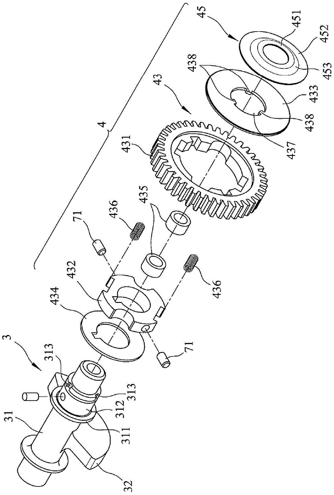
[0019] refer to image 3 , 4 , is the first preferred embodiment of the auxiliary device 4 of the balance shaft 3 of the present invention, the balance shaft 3 is pivotally arranged in a crankcase 5, and a positioning unit 6 is provided in the crankcase 5, and the positioning unit 6 includes a A first rotating bearing 61 and a second rotating bearing 62 . The balance shaft 3 includes a shaft 31 pivotally disposed in a crankcase 5 , and a counterweight 32 located on the shaft 31 . The first rotating bearing 61 includes a fixed outer ring 611 , a movable inner ring 612 disposed inside the fixed outer ring 611 , and a ball 613 disposed between the fixed outer ring 611 and the movable inner ring 612 . Similarly, the second rotating bearing 62 also includes a fixed outer ring 621, a movable inner ring 622 disposed inside the fixed outer ring 621, and a movable inner ring 622 disposed between the fixed outer ring 621 and the movable inner ring 622. Ball 623. Two ends of the shaf...


PUM


Abstract

The invention provides an auxiliary device for a balance shaft. The balance shaft is arranged in a crank case in a pivotal mode. A locating unit is arranged in the crank case. The balance shaft comprises a shaft rod, and a balance weight located on the shaft rod, wherein the shaft rod is arranged on the locating unit and can rotate relative to the locating unit. The auxiliary device comprises a damping unit and a straining element, wherein the damping unit is arranged on the shaft rod and is close to the locating unit, and the straining element is arranged on the shaft rod and located between the locating unit and the damping unit. The straining element is provided with the small-caliber end and the large-caliber end, wherein the small-caliber end penetrates through the shaft rod and is used for abutting against the locating unit, and the large-caliber end is opposite to the small-caliber end and is used for abutting against the damping unit. By means of the auxiliary device, the axial gap of the balance shaft can be eliminated, and abnormal noise can be avoided.

Description

technical field [0001] The present invention relates to an auxiliary device, in particular to an auxiliary device for a balance shaft of an engine. Background technique [0002] refer to figure 1 , 2 Generally, the engine includes a crankcase 11, a crankshaft 12 pivotally connected in the crankcase 11, a balance shaft 13 pivotally connected in the crankcase 11 and interlocking with the crankshaft 12, a gear mechanism 14, and a Buffer assembly 15. The crankshaft 12 has a driving gear portion 121 . The balance shaft 13 has a shaft 131 pivotally disposed in the crankcase 11 , and a counterweight 132 located on the shaft 131 . The gear mechanism 14 includes a set of driven gear 141 arranged on the shaft 131 and meshed with the driving gear part 121 , a fixed plate passing through the shaft 31 and covering one side of the driven gear 141 142. A C-shaped clasp 143 buckled on the shaft 131 and stuck on the fixed piece 142, an inner ring 144 located in the driven gear 141 and s...

Claims


Application Information

Patent Timeline
Patent Type & Authority Patents(China)
IPC IPC(8): F16F15/28F16F15/121
CPCF16F15/123F16F15/283
Inventor 郭伟信李俊敬
Owner KYMCO
Why Eureka
Try Eureka