
Photomask for laser radar, preparation method of photomask and laser radar

A technology of laser radar and photomask, which is applied in the field of photoelectric detection, can solve the problems of affecting appearance, overflow, glue overflow, etc., and achieve the effects of beautifying the appearance, reducing electromagnetic radiation, and enhancing the ability to shield electromagnetic interference

Pending Publication Date: 2022-07-15
HESAI TECH CO LTD
View PDF0 Cites 1 Cited by
  • Summary
  • Abstract
  • Description
  • Claims
  • Application Information

AI Technical Summary

Problems solved by technology

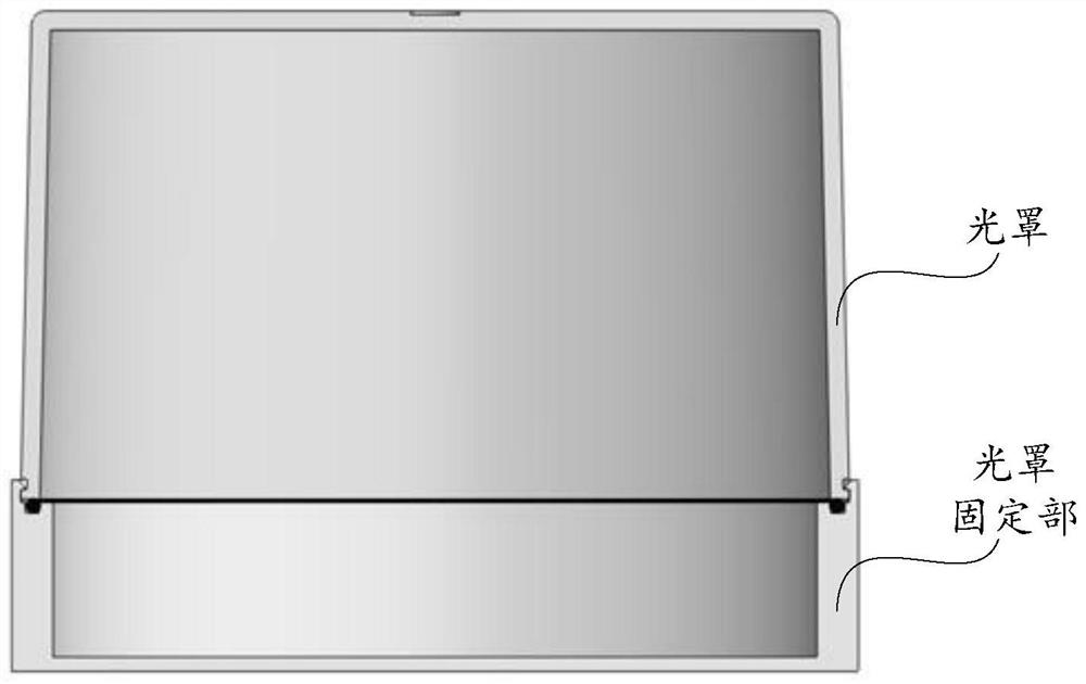
[0004] The existing lidar mostly uses snap-on masks made of PC materials, such as Figure 1a As shown, since the PC material is an insulator, the insulator cannot conduct with the fixed part of the photomask, so that the lidar after the photomask is installed cannot shield electromagnetic interference, and cannot meet the requirements of the electromagnetic compatibility of the vehicle standard
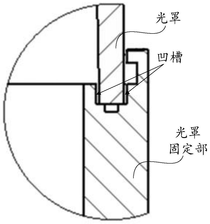
Figure 1b for Figure 1a Partial enlarged view of the snap-on photomask design, the groove will be filled with adhesive, and when the protrusion at the lower end of the photomask is crimped into the side groove of the photomask fixing part, it will be pressed downward, making Adhesive overflows from the left and right sides of the groove (the gap of the buckle), and there will be obvious glue overflow problems, which will affect the appearance

Method used


Image

  • Photomask for laser radar, preparation method of photomask and laser radar
  • Photomask for laser radar, preparation method of photomask and laser radar
  • Photomask for laser radar, preparation method of photomask and laser radar

Examples


Embodiment Construction

[0062] In the following, only certain exemplary embodiments are briefly described. As those skilled in the art would realize, the described embodiments may be modified in various different ways, all without departing from the spirit or scope of the present invention. Accordingly, the drawings and description are to be regarded as illustrative in nature and not restrictive.

[0063] In the description of the present invention, it should be understood that the terms "center", "longitudinal", "lateral", "length", "width", "thickness", "upper", "lower", "front", " Or The positional relationship is based on the orientation or positional relationship shown in the accompanying drawings, which is only for the convenience of describing the present invention and simplifying the description, rather than indicating or implying that the referred device or element must have a specific orientation, be constructed and operated in a specific orientation, Therefore, it should not be construed...


PUM

PropertyMeasurementUnit
transmittivityaaaaaaaaaa

Abstract

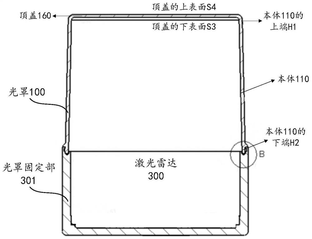
The invention provides a photomask for a laser radar, a preparation method of the photomask and the laser radar, the laser radar comprises a photomask fixing part, the photomask is installed on the photomask fixing part, and the photomask comprises a body which is provided with an inner surface and an outer surface opposite to the inner surface; and the first light-transmitting conductive film is arranged on the body and covers the inner surface or the outer surface, and the first light-transmitting conductive film is connected and conducted with the photomask fixing part, so that the laser radar can shield electromagnetic interference. According to the photomask designed by the invention, the electromagnetic interference shielding capability of the laser radar can be greatly enhanced, and the electromagnetic radiation of the laser radar to the outside is reduced, so that the laser radar has electromagnetic compatibility, and the requirement of vehicle-gauge-level electromagnetic compatibility is met.

Description

technical field [0001] The invention relates to the field of photoelectric detection, in particular to a photomask for laser radar, a preparation method thereof, and a laser radar. Background technique [0002] With the rise of autonomous driving technology, lidar has been paid more and more attention as an important detection component. Lidar, as its name implies, is a radar system that emits a laser beam to detect the position, velocity and other characteristic quantities of a target. Its working principle is to emit a probe beam to the target, and then compare the received echo beam reflected from the target with the probe beam, and after proper processing, the relevant information of the target can be obtained, such as target distance, azimuth, altitude, Parameters such as speed, attitude, and even shape can be used to detect, track and identify targets such as aircraft and missiles. [0003] As a vehicle-grade product, lidar has high requirements for EMC (Electromagne...

Claims


Application Information

Patent Timeline
Patent Type & Authority Applications(China)
IPC IPC(8): G01S7/481G02B1/11G02B1/14H05K9/00
CPCG01S7/4813G02B1/11G02B1/14H05K9/0058H05K9/0084
Inventor 朱康刘思远韩英龚海峰向少卿
Owner HESAI TECH CO LTD
Learn More