
Industrial chimney ladder stand detection equipment

A detection equipment and ladder-climbing technology, which is applied in the field of industrial chimney ladder detection equipment, can solve problems such as ladder breakage, difficult operation, and safety accidents, and achieve the effect of easy maintenance

Pending Publication Date: 2022-07-15
何志明
View PDF0 Cites 0 Cited by
  • Summary
  • Abstract
  • Description
  • Claims
  • Application Information

AI Technical Summary

Problems solved by technology

[0005] In order to overcome the long-term use of the ladder, the ladder breaks, and the staff are prone to safety accidents during the climbing process. However, in the existing detection methods, manual detection is often used. Due to the high-altitude detection, the operation The disadvantage of high difficulty, the present invention provides an industrial chimney ladder detection equipment

Method used


Image

  • Industrial chimney ladder stand detection equipment
  • Industrial chimney ladder stand detection equipment
  • Industrial chimney ladder stand detection equipment

Examples


Embodiment 1

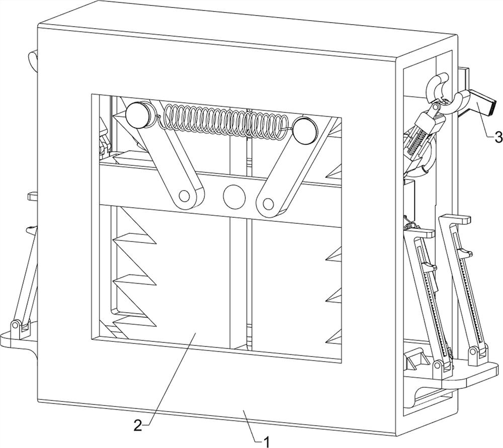
[0031] An industrial chimney climbing ladder detection equipment, such as Figure 1-10 As shown, it includes an installation frame 1, a detection system 2 and a marking system 3; a detection system 2 is installed inside the installation frame 1; a marking system 3 is connected to the front of the detection system 2.

[0032] First, the staff moves and fixes the industrial chimney ladder detection equipment on the chimney ladder, and then controls the detection system 2 to drive the industrial chimney ladder detection equipment to move up, and at the same time, detects the ladder on the chimney. When the side of the ladder on the chimney is detected When broken, the linkage marking system 3 marks the damaged parts at the same time, which is convenient for maintenance personnel to repair.

Embodiment 2

[0034] On the basis of Example 1, as Figure 1-10As shown, the detection system 2 includes a telescopic plate 201, a first bearing seat 202, a sliding frame 203, a first elastic member 204, a first limit block 205, a first electric push rod 206, a wedge block 207, a toothed plate 208, Fixed frame 209, sliding rod 2010, first connecting plate 2011, limit shaft 2012, second elastic member 2013, limit rod 2014, second bearing seat 2015, telescopic rod 2016 and electric clip 2017; the internal fixation of installation frame 1 A toothed plate 208 is connected; a through chute is set on the toothed plate 208, and a sliding rod 2010 is slidably connected in the through chute; The lower part of 209 is hinged with two left-right symmetrical first electric push rods 206; the telescopic ends of the two first electric push rods 206 are hinged with a telescopic plate 201; the upper surface of the telescopic plate 201 is fixedly connected with four rectangularly distributed The first beari...


PUM


Abstract

The invention relates to the related technical field of chimney detection, in particular to industrial chimney ladder stand detection equipment. The technical problems that due to the fact that a crawling ladder is used for a long time, the crawling ladder is broken, safety accidents are extremely prone to occurring in the climbing process of workers, however, in an existing detection mode, a manual mode is usually adopted for detection, and due to high-altitude detection, the operation difficulty is too high are solved. According to the technical scheme, the industrial chimney ladder stand detection equipment comprises a mounting frame, a detection system and a marking system, a detection system for detecting the crawling ladder is mounted in the mounting frame; and the front part of the detection system is connected with a marking system for marking the damaged crawling ladder. According to the invention, regular detection of the ladder climbing rod on the chimney is realized, multi-angle rotation debugging is carried out by utilizing a method of moving on the chimney according to different fracture angles of the ladder climbing rod, so that the fracture area of the ladder climbing rod is more thoroughly detected, and the detected ladder climbing rod is marked, so that maintenance personnel can conveniently carry out maintenance.

Description

technical field [0001] The invention relates to the related technical field of chimney detection, in particular to an industrial chimney climbing ladder detection device. Background technique [0002] Industrial chimneys are generally composed of: concrete wall, insulation layer, inner wall and anti-corrosion layer. The inner wall includes the inner lining and the inner cylinder. During the use of the chimney, there will be slippage between the memory and the concrete wall due to the different thermal expansion and heating temperature of the respective materials, resulting in a gap. The ladder on the outer surface of the chimney is horizontal. U-shaped, due to various weather and other reasons, the ladder on the chimney is corroded and broken. [0003] In the prior art, because the ladder of the chimney needs to be used frequently, but in the process of climbing, due to the long-term use of the ladder, the ladder is broken, and the staff is very prone to safety accidents du...

Claims


Application Information

Patent Timeline
Patent Type & Authority Applications(China)
IPC IPC(8): G01M13/00G01N3/02G01N3/08
CPCG01M13/00G01N3/02G01N3/08
Inventor 何志明
Owner 何志明
Learn More