
emergency light system

An emergency light and signal technology, which is applied in the layout of electric light circuits, lighting devices, light sources, etc., can solve the problems that the state cannot be detected, the emergency light lacks monitoring, and the emergency light has no external network communication function. Conducive to inspection and self-inspection, easy to install

Active Publication Date: 2018-01-19
SHANGHAI EASTSOFT MICROELECTRONICS
View PDF5 Cites 0 Cited by
  • Summary
  • Abstract
  • Description
  • Claims
  • Application Information

AI Technical Summary

Problems solved by technology

[0003] However, the emergency lights in the prior art lack monitoring, their status cannot be detected, and the emergency lights have no communication function with the external network

Method used


Image

  • emergency light system
  • emergency light system
  • emergency light system

Examples


Embodiment 1

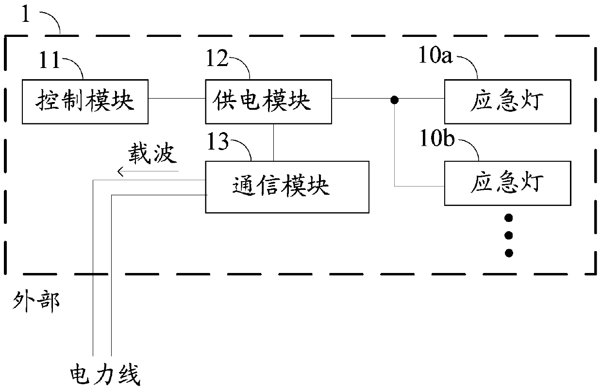
[0077] Such as figure 1 An emergency light system 1 shown includes: several emergency lights (10a, 10b, . . . ), a control module 11 , a power supply module 12 and a communication module 13 . in:

[0078] The control module 11 is adapted to output a working signal for controlling the working state of one or more emergency lights. The working state of the emergency light includes the main working state and the emergency working state. In the main working state, the emergency light is illuminated based on the DC power supply provided by the normal life voltage / AC voltage 220V, while in the emergency working state, the emergency light is illuminated based on the battery power supply. Work.

[0079] The power supply module 12 is suitable for receiving working signals. The control module 11 uses the conversion of the working signal to control the power supply module 12 to provide corresponding DC power or battery power for the emergency light to control the working state of the ...

Embodiment 2

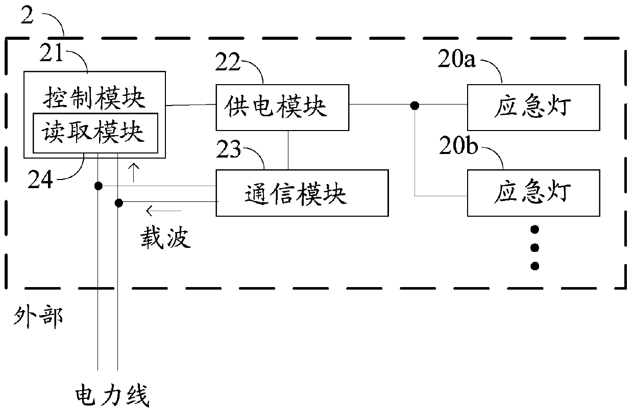
[0086] Such as figure 2 The shown emergency light system 2 includes: several emergency lights (20a, 20b, . . . ), a control module 21 , a power supply module 22 and a communication module 23 . Different from Embodiment 1, in this embodiment, the control module 21 further includes a reading module 24 .

[0087] The reading module 24 is adapted to read the above-mentioned centralized control signal based on the power line. The centralized control signal transmitted on the power line is transmitted in the form of a carrier wave, so the reading module 24 needs to analyze and obtain the above-mentioned centralized control signal.

[0088] The control module 21 also outputs a working signal for controlling the working state of the emergency light based on the centralized control signal.

Embodiment 3

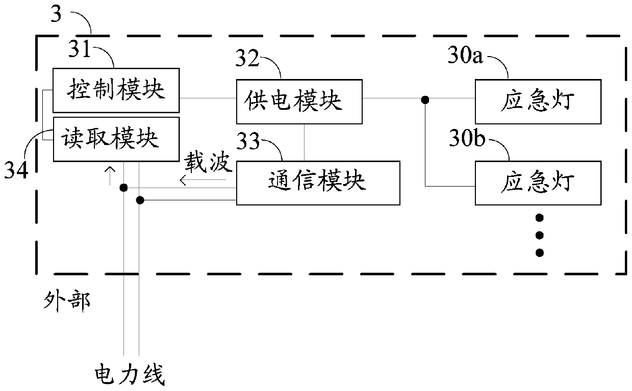
[0090] Such as image 3 An emergency light system 3 shown includes: several emergency lights (30a, 30b, . . . ), a control module 31 , a power supply module 32 , a communication module 33 and a reading module 34 . Different from Embodiment 2, in this embodiment, the reading module 34 is independent from the control module 31 .


PUM


Abstract

The invention relates to an emergency lamp system comprising a control module, a power supply module, and a communication module. The control module is suitable for outputting a working signal used for controlling the working states of emergency lamps, wherein the working states include a main working state and an emergency working state. The power supply module is suitable for connecting the emergency lamp system to a power supply according to the working signal, wherein the power supply is a direct-current power supply when the working signal is a first signal used for making the emergency lamps go into the main working state, and the power supply is a battery power supply when the working signal is a second signal used for making the emergency lamps go into the emergency working state. The communication module is suitable for coupling an information source signal about the working states of the emergency lamps and a carrier signal and transferring a coupling signal to an external centralized controller. With the emergency lamp system, the emergency lamps can be monitored and detected.

Description

technical field [0001] The invention relates to the field of light control, in particular to a power line carrier emergency light system. Background technique [0002] Emergency lights are an indispensable and important component of the fire safety system; emergency lights are mandatory to be installed in public buildings, high-rise buildings, hotels, and crowded places and require regular maintenance. The function of the emergency light is to provide the minimum illumination for the designated safe passage within a specific time when the general lighting in the building cannot work normally due to fire or other unpredictable disasters. Emergency lights can also provide lighting signal signs to help safe evacuation when the general lighting in the building does not work normally, and clearly indicate the direction change of each channel to help trapped people evacuate in an orderly and safe manner. [0003] However, the emergency lights in the prior art lack monitoring, the...

Claims


Application Information

Patent Timeline
Patent Type & Authority Patents(China)
IPC IPC(8): H05B37/02
Inventor 杨荣陈光胜潘松
Owner SHANGHAI EASTSOFT MICROELECTRONICS
Learn More