Water supply recirculation valve protection system

A recirculation valve and protection system technology, applied in the boiler feed water field, can solve the problems affecting the economy and safety of the unit, increase the coal consumption of the unit, increase the power consumption of the feed water pump, etc., so as to improve the economy and safety, and reduce maintenance The effect of maintenance frequency and service life extension

Pending Publication Date: 2022-07-15
HUANENG LINYI POWER GENERATION CO LTD
View PDF0 Cites 0 Cited by
  • Summary
  • Abstract
  • Description
  • Claims
  • Application Information

AI Technical Summary

Problems solved by technology

[0003] Due to the high water pressure on the side of the feed water pump and the low water pressure on the side of the deaerator, the pressure difference on both sides of the feed water recirculation valve is very large. When matched with a supercritical (or ultra-supercritical) unit, the pressure difference can reach more than 25MPa , affected by the load of the unit and the fluctuation of the power grid, the start-stop and flow adjustment of the feed water pump are very frequent, resulting in frequent on-off of the recirculation pipeline, and the water recirculation valve is washed frequently and strongly, which is easily caused by the wear of the valve core. Leakage, high cost of repair and maintenance, when a large leak occurs, it needs to be temporarily shut down for replacement, and the leakage will also increase the power consumption (steam consumption) of the feed water pump and increase the coal consumption of the unit. For a 600MW unit, the water supply Every time the recirculation valve leaks 10% of the feed water flow, the coal consumption of the unit will increase by about 0.6g / (kW·h), seriously affecting the economy and safety of the unit during operation

Method used


Image

  • Water supply recirculation valve protection system

Examples


Embodiment Construction

[0021] The preferred embodiments of the present invention will be described in detail below with reference to the accompanying drawings, so that the advantages and features of the present invention can be more easily understood by those skilled in the art, and the protection scope of the present invention can be more clearly defined.

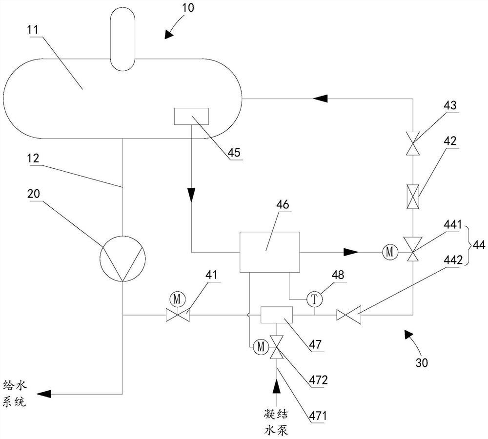
[0022] like figure 1 As shown, the water supply recirculation valve protection system provided by the present invention includes an electric shut-off valve 41, a water supply recirculation valve 42, and a manual shut-off valve 43 sequentially arranged on the water supply recirculation pipeline 30, wherein the water supply recirculation pipeline 30 One end is communicated with the outlet of the feed water pump 20, the other end is communicated with the water tank 11 of the deaerator 10, the inlet of the feed pump 20 is communicated with the water outlet of the water tank 11, and the electric cut-off valve 41 is located in the water supply recircul...


PUM


Abstract

The invention provides a water supply recirculation valve protection system which comprises an electric stop valve, a pressure reduction assembly, a water supply recirculation valve and a manual stop valve which are sequentially arranged on a water supply recirculation pipeline, a controller, and a pressure measurement device which is arranged on a deaerator water tank and is used for measuring the pressure value of the water tank, the electric stop valve is located on the side, close to the water feeding pump, of the water feeding recirculation pipeline, the pressure reduction assembly is arranged, the upstream pressure of the water feeding recirculation valve can be reduced through the pressure reduction assembly, and therefore the washing degree is reduced, the service life is prolonged, the overhaul and maintenance frequency is reduced, leakproofness is ensured, and the leakage rate is reduced; the controller is electrically connected with the adjustable pressure reducing valve and the pressure measuring device, and the pressure reducing proportion of the adjustable pressure reducing valve can be controlled in real time according to the pressure value of the water tank, so that the front-back pressure difference of the water supply recirculation valve is reduced to the maximum extent while the recirculation water power is guaranteed, and the economical efficiency and safety of a unit during operation are remarkably improved.

Description

technical field [0001] The invention belongs to the technical field of boiler water supply, and in particular relates to a water supply recirculation valve protection system. Background technique [0002] At present, the feed pumps used in thermal power plants are high-temperature and high-pressure multi-stage centrifugal pumps. In order to ensure the normal start and stop of the feed pumps, a recirculation pipeline is designed. The pipeline is generally led from the outlet of the feed water pump and returned to the feed water recirculation valve. To the deaerator, the main functions of this pipeline are: (1) before the feed pump is started, the pump is filled by connecting the recirculation pipeline; (2) when the demand decreases sharply, the recirculation pipeline is connected by connecting the pump. Realize the diversion, gradually reduce the flow of the feed pump, and avoid the damage of the feed pump due to sudden changes in the flow. [0003] Due to the high water pre...

Claims


Application Information

Patent Timeline
Patent Type & Authority Applications(China)
IPC IPC(8): F22D5/34F22D11/02F22D1/50
CPCF22D5/34F22D11/02F22D1/50
Inventor 张雨翔
Owner HUANENG LINYI POWER GENERATION CO LTD
Why Eureka
Try Eureka