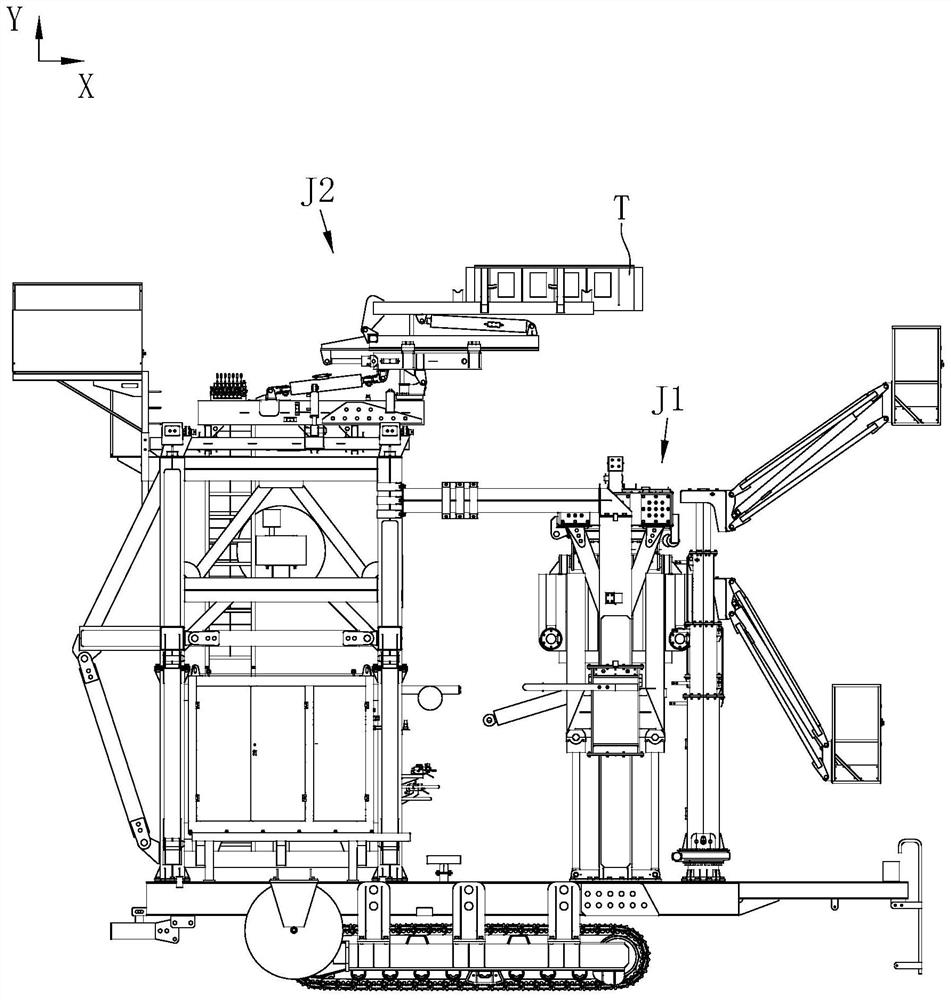
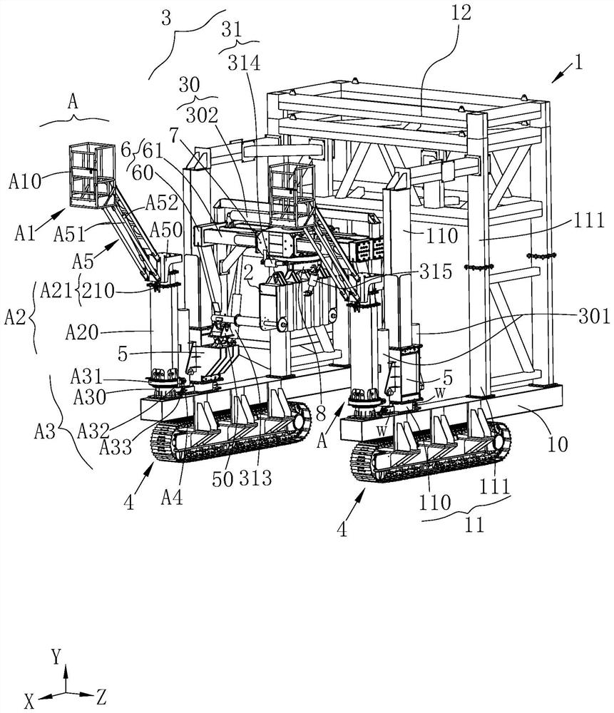
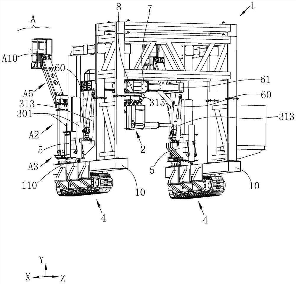
Middle partition wall mounting equipment with top bracket mounting mechanism

An installation mechanism and installation equipment technology, applied in shaft equipment, mining equipment, shaft lining and other directions, can solve the problems of short construction distance, poor flexibility, damage to partition walls, etc., and achieve long extension distance, high alignment accuracy, and convenient installation. Effect

Pending Publication Date: 2022-07-15
CCCC TUNNEL ENG
View PDF0 Cites 0 Cited by
  • Summary
  • Abstract
  • Description
  • Claims
  • Application Information

AI Technical Summary

Problems solved by technology

[0006] 1. The existing installation mechanism is large in size, difficult to move in a narrow tunnel, poor in flexibility, and difficult to meet the installation requirements of top corbels at different positions;
[0007] 2. Limited by the space of the tunnel, the existing installation mechanism can achieve a short construction distance and lack of sufficient installation space. It is easy to collide with the middle partition wall during installation and cause damage

Method used


Image

  • Middle partition wall mounting equipment with top bracket mounting mechanism
  • Middle partition wall mounting equipment with top bracket mounting mechanism
  • Middle partition wall mounting equipment with top bracket mounting mechanism

Examples


Embodiment Construction

[0050] In order to make the above objects, features and advantages of the present application more clearly understood, the specific embodiments of the present application will be described in detail below with reference to the accompanying drawings. In the following description, numerous specific details are set forth in order to provide a thorough understanding of the present application. However, the present application can be implemented in many other ways different from those described herein, and those skilled in the art can make similar improvements without departing from the connotation of the present application. Therefore, the present application is not limited by the specific embodiments disclosed below.

[0051] In the description of this application, it should be understood that the terms "center", "longitudinal", "lateral", "length", "width", "thickness", "upper", "lower", "front", " Back, Left, Right, Vertical, Horizontal, Top, Bottom, Inner, Outer, Clockwise, Co...


PUM


Abstract

The invention relates to mid-partition wall mounting equipment with a top bracket mounting mechanism, which comprises a mid-partition wall turnover mechanism, a top bracket mounting mechanism, a top bracket mounting mechanism and a top bracket mounting mechanism, the top bracket mounting mechanism comprises a mounting base, an overturning component, a jacking component and a lifting component, the jacking component comprises a body and a jacking module, an avoiding notch is formed in the body, the jacking module is arranged on the body, the overturning component comprises a first frame rod and a second frame rod, the first frame rod is rotationally connected to the mounting base in the Z-axis direction, and the second frame rod is rotationally connected to the mounting base in the Z-axis direction; the body is rotationally connected to the second frame rod in the Z-axis direction, and the top bracket mounting mechanism has an unfolded state and a folded state. On one hand, the mounting mechanism can be flexibly switched between the unfolding state and the folding state, and the requirement for mounting the top bracket in any narrow tunnel is met; and on the other hand, in the unfolded state, the body is long in extension distance and high in alignment precision with a top bracket, and the body can conveniently move along the surface of the middle partition wall to implement installation.

Description

technical field [0001] The invention belongs to the technical field of tunnel engineering, and in particular relates to a middle partition wall installation device with a top corbel installation mechanism. Background technique [0002] As we all know, a tunnel is a building built underground, underwater or in a mountain, and laid a railway or built a road for the passage of motor vehicles. The construction process of a tunnel mainly includes tunnel planning, survey, design, penetration control measurement and construction, etc. Therefore, whether it is construction or use, the tunnel process is cumbersome and complicated. [0003] However, in a shield tunnel designed with a partition wall, the partition wall is an important part of the tunnel structure as a structure that physically separates the left and right driving spaces. [0004] At present, in the construction of the middle partition wall of the tunnel, in order to facilitate transportation, the prefabricated partiti...

Claims


Application Information

Patent Timeline
IPC IPC(8): E21D11/40
CPCE21D11/40
Inventor 朱美恒杨光秦乐徐云龙高俊华卢俊杰张晓锋郝玉双吴双闫海磊
Owner CCCC TUNNEL ENG
Why Eureka
Try Eureka