
Ice hockey continuous conveying device and conveying method

A conveying device, ice puck technology, applied in conveyors, transportation and packaging, loading/unloading, etc., can solve problems such as low deterrence, inability to meet the requirements of the ocean-going carrier's own defense capability, and discontinuous launch, and improve law enforcement. effect of ability

Pending Publication Date: 2022-07-15
CHINA SHIP DEV & DESIGN CENT
View PDF0 Cites 0 Cited by
  • Summary
  • Abstract
  • Description
  • Claims
  • Application Information

AI Technical Summary

Problems solved by technology

However, the current ice hockey water cannon still has certain problems, such as long firing intervals and discontinuous firing, so its deterrent effect is not high, and it cannot meet the law enforcement requirements of official ships and the self-defense requirements of ocean-going transport ships.

Method used


Image

  • Ice hockey continuous conveying device and conveying method
  • Ice hockey continuous conveying device and conveying method
  • Ice hockey continuous conveying device and conveying method

Examples


Embodiment 1

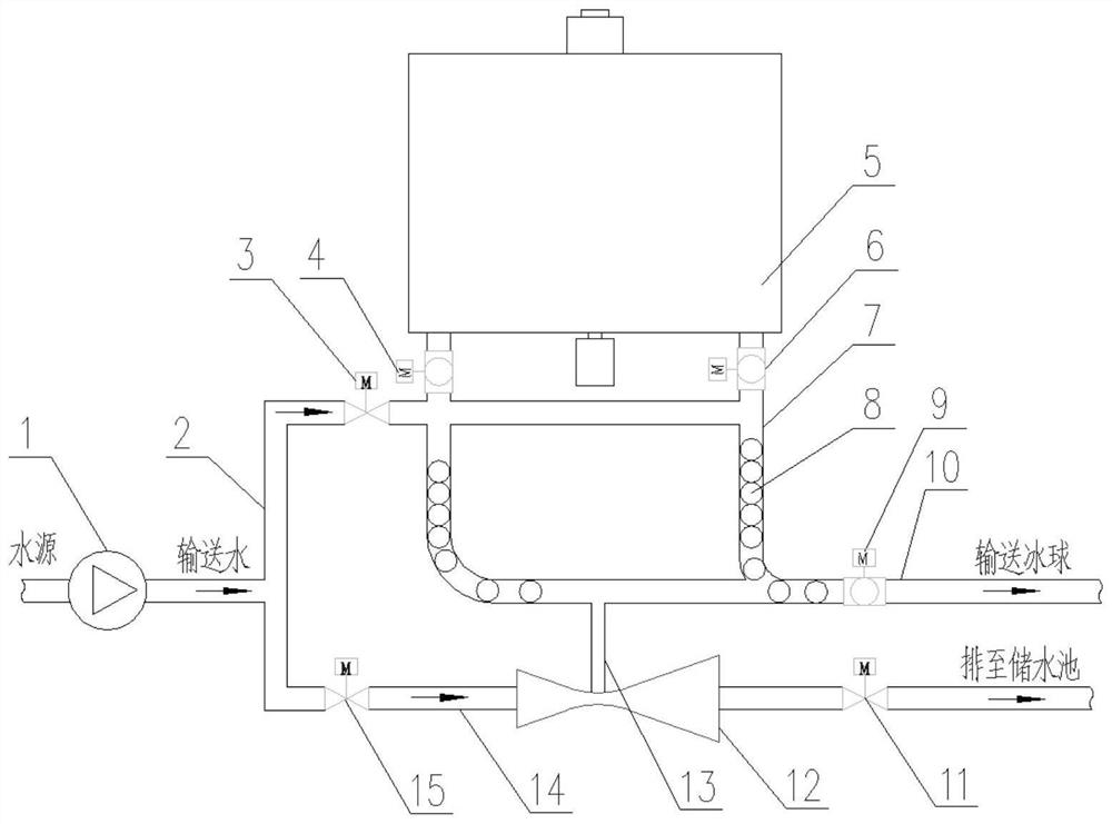
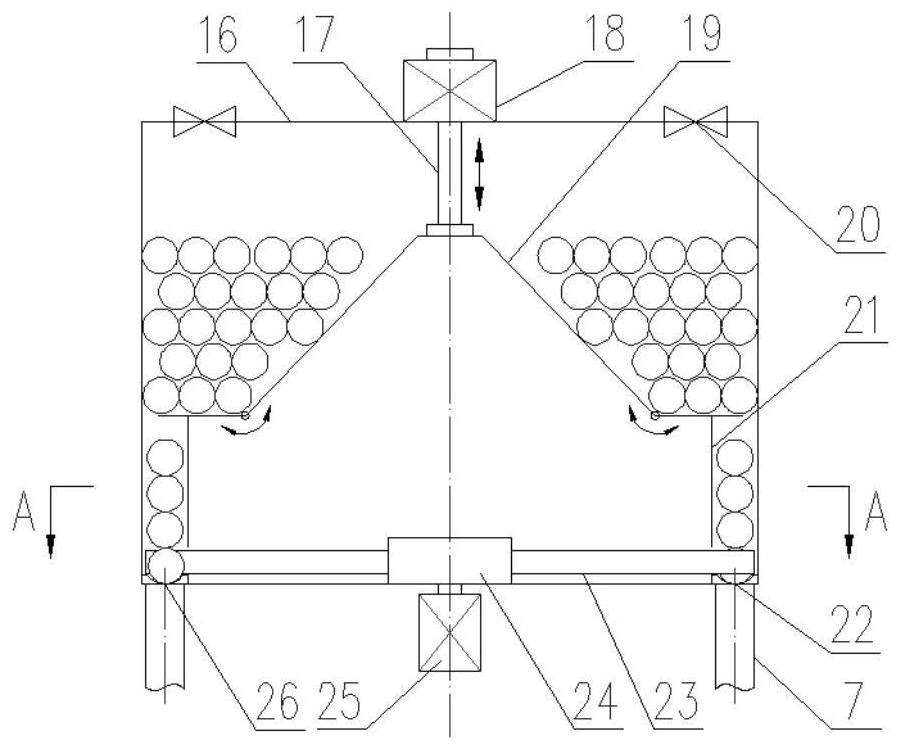
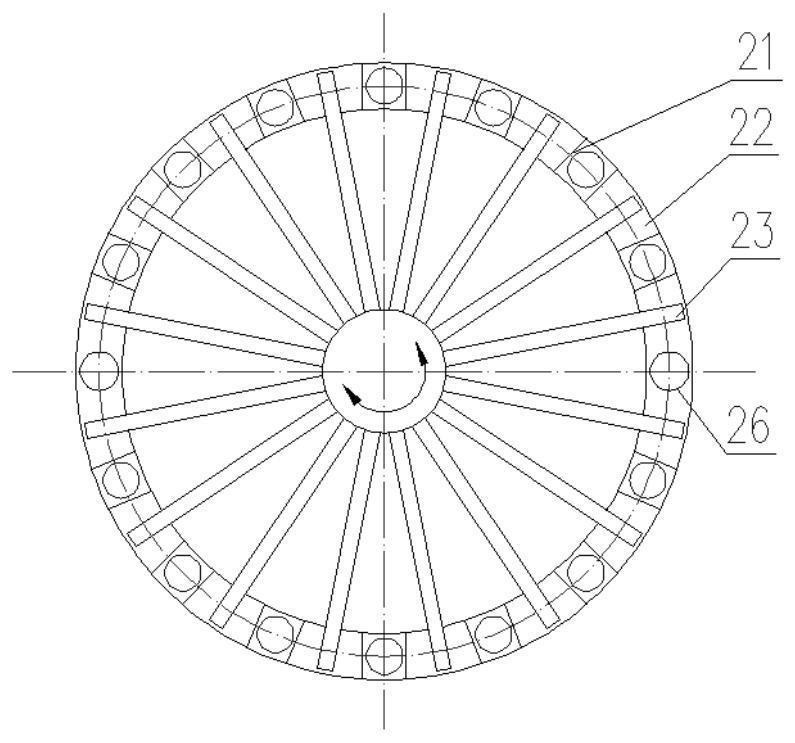
[0045] see Figure 1-Figure 3 , An ice hockey continuous conveying device, which comprises a water supply mechanism, an ice hockey continuous conveying mechanism and a drainage mechanism. The water supply mechanism is respectively connected with the ice hockey continuous conveying mechanism and the drainage mechanism, and is used for providing high-pressure water to the ice hockey continuous conveying mechanism and the drainage mechanism. The ice ball continuous conveying mechanism includes an ice ball storage box 5 with ice balls 8, a ball drop pipe 7 with a ball drop valve, and an ice ball conveying pipeline 10 with an ice ball conveying valve 9. The ice ball storage box 5 is provided with a rotating mechanism, and the rotation mechanism rotates the ice balls. The ice balls 8 in the storage box 5 are continuously transported to the drop tube 7, and the drop tube 7 is connected to the ice ball conveying pipeline 10 through a bend. The drainage mechanism is used for draining ...

Embodiment 2

[0054] A method for continuously transporting ice balls using the above-mentioned ice ball continuous conveying device, comprising the following steps:

[0055] Open the drain valve 11 and the water supply bypass valve 15 in turn, close the water supply valve 3, the water pump 1 provides working water to the jet pump 12, and the jet pump 12 uses the principle of high-speed jet suction to empty the water in the ice ball conveying pipe 10; After the water is drained, close the drain valve 11 and the water supply bypass valve 15;

[0056] Start the reciprocating motor 18 and the rotating motor 25, open the ball drop valve, the reciprocating motor 18 drives the push-pull rod 17 to move up and down, the push-pull rod 17 drives the foldable support plate 19 to move up and down, the foldable support plate 19 rises and drives the lower edge to move inward to form a gap , the ice ball 8 falls into the vertical positioning groove 21 from the gap, then falls into the rolling groove 22, a...


PUM


Abstract

The invention discloses a continuous ice hockey conveying device which comprises a water supply mechanism, a continuous ice hockey conveying mechanism and a drainage mechanism. The water supply mechanism is respectively connected with the ice ball continuous conveying mechanism and the water drainage mechanism and is used for providing high-pressure water for the ice ball continuous conveying mechanism and the water drainage mechanism; the ice ball continuous conveying mechanism comprises an ice ball storage box containing ice balls, a ball falling pipe with a ball falling valve and an ice ball conveying pipeline with an ice ball conveying valve, a rotating mechanism is arranged in the ice ball storage box, the rotating mechanism rotates to continuously convey the ice balls in the ice ball storage box to the ball falling pipe, and the ball falling pipe is communicated with the ice ball conveying pipeline; and the drainage mechanism is used for draining water in the ice hockey conveying pipeline before the ice hockey continuous conveying mechanism formally conveys the ice hockey. The invention further provides an ice ball continuous conveying method. The ice hockey can be continuously launched, and the law enforcement ability of an official ship and the deterrent force of a far-distance transport ship are improved.

Description

technical field [0001] The invention belongs to the technical field of high-pressure fluid transportation, and in particular relates to an ice ball continuous transportation device and a transportation method. Background technique [0002] Water cannon is a fire protection system that can extinguish fires from a long distance by spraying water medium at high pressure, and can also be used as a soft weapon for ships. The water cannon system is now widely used in government ships such as coast guard ships and maritime ships. It is an important soft weapon for government ships to carry out law enforcement strikes. [0003] Some waters in Somalia are escorted by the navies of China and other countries and are relatively safe. However, when ocean-going transport ships sail in most other waters without escort, the danger still exists. In West Africa, the Gulf of Guinea, the South Philippines, the Straits of Malacca and other anchorages outside the waters, the activities of pirate...

Claims


Application Information

Patent Timeline
Patent Type & Authority Applications(China)
IPC IPC(8): B65G51/01B65G65/48B65G65/00
CPCB65G51/01B65G65/4809B65G65/005
Inventor 汪震王书文胡洋洋高瀚林卜用暹
Owner CHINA SHIP DEV & DESIGN CENT
Learn More