
Automatic delivery and conveying device for vaccine drugs

A transmission device and medicine technology, which is applied in the field of medicine transmission, can solve problems such as labor-intensive, unsatisfactory use needs, etc., and achieve the effect of increasing the delivery rate, reducing labor costs, and stabilizing the coding

Pending Publication Date: 2022-07-15
荀其飞
View PDF0 Cites 0 Cited by
  • Summary
  • Abstract
  • Description
  • Claims
  • Application Information

AI Technical Summary

Problems solved by technology

[0004] The purpose of the present invention is to solve the problem in the prior art that the delivery of vaccine medicines is usually carried out by means of a conveyor belt, which is simple and convenient, and can effectively transport vaccine medicines out of the warehouse, but in the process of transmission, manual coding is required , laborious and labor-intensive, and can not meet the shortcomings of the use requirements, and proposes an automatic delivery device for vaccines and medicines out of the warehouse

Method used


Image

  • Automatic delivery and conveying device for vaccine drugs
  • Automatic delivery and conveying device for vaccine drugs
  • Automatic delivery and conveying device for vaccine drugs

Examples


Embodiment 1

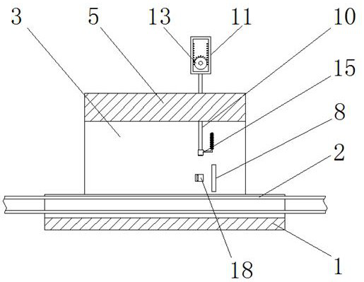
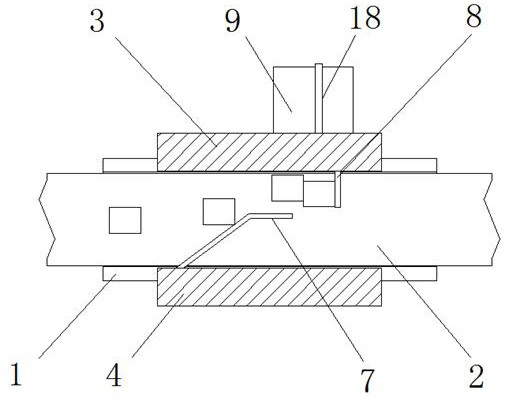
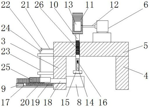
[0027] refer to Figure 1-5 , an automatic delivery transmission device for vaccines and medicines, comprising a transmission casing 1, a transmission belt 2 is arranged in the transmission casing 1, and a first side plate 3 and a second side plate 4 are fixedly connected to the transmission casing 1 by welding. , the tops of the first side plate 3 and the second side plate 4 are fixedly connected with the same top plate 5 by welding, the top of the top plate 5 is fixedly installed with the motor 6 by bolts, and the inner wall of the second side plate 4 is fixedly connected by welding with a guide plate 7. An intercepting plate 8 is fixedly connected to the inner wall of the first side plate 3 by welding, and a horizontal plate 9 is fixedly connected to the outer side of the first side plate 3 by welding. The horizontal plate 9 is provided with a push rod mechanism, and the top plate 5 slides on A coding mechanism is installed, and both the push rod mechanism and the coding me...

Embodiment 2

[0037] The difference from the first embodiment is that it includes a transmission casing 1, a transmission belt 2 is arranged in the transmission casing 1, and a first side plate 3 and a second side plate 4 are fixedly connected to the transmission casing 1, and the first side plate 3 and the second side plate 4 are fixedly connected. The same top plate 5 is fixedly connected to the top of the side plate 3 and the second side plate 4, the motor 6 is fixedly installed on the top of the top plate 5, the guide plate 7 is fixedly connected to the inner wall of the second side plate 4, and the inner wall of the first side plate 3 is fixedly connected. The intercepting plate 8 is fixedly connected to the top, and the outer side of the first side plate 3 is fixedly connected to a horizontal plate 9. The horizontal plate 9 is provided with a push rod mechanism, and the top plate 5 is slidably installed with a coding mechanism, a push rod mechanism and a coding mechanism. Both are matc...


PUM


Abstract

The invention belongs to the field of medicine conveying, particularly relates to an automatic delivery and conveying device for vaccine drugs, and aims to solve the problems that the existing vaccine drugs are usually conveyed by a conveying belt, are simple and convenient and can be effectively conveyed out of a warehouse, but manual delivery code spraying is needed in the conveying process, time and labor are wasted, and the efficiency is high. According to the technical scheme, the device comprises a conveying shell, a conveying belt is arranged in the conveying shell, a first side plate and a second side plate are fixedly connected to the conveying shell, the top of the first side plate and the top of the second side plate are fixedly connected with the same top plate, and a motor is fixedly installed at the top of the top plate; when in use, the automatic code spraying device can automatically intercept and spray codes on delivered vaccine drugs, is high in automation degree and stable in code spraying, effectively improves the delivery rate of the vaccine drugs, and reduces the labor expenditure.

Description

technical field [0001] The invention relates to the technical field of medicine transmission, in particular to an automatic delivery transmission device for vaccine medicines. Background technique [0002] With the vigorous development of the biotechnology industry, vaccine products and types in the pharmaceutical market are showing a trend of rapid growth, and the storage of vaccines has become a huge problem. At present, most disease prevention and control institutions and inoculation units still use refrigerators and freezers. The storage of vaccine drugs in the form of (cabinet) and small cold storage is bound to bring disadvantages such as crowded space, high cost investment, difficulty in personnel operation, difficulty in inventory, difficulty in recording the temperature of the cold chain of vaccine drugs, and poor traceability of related data information. [0003] In recent years, computer information systems, automatic control technology and automatic identificatio...

Claims


Application Information

Patent Timeline
IPC IPC(8): B65G47/22B65G47/88B65G15/30B65G21/08B41J3/407
CPCB65G47/22B65G47/88B65G15/30B65G21/08B41J3/407
Inventor 荀其飞林汝菲
Owner 荀其飞
Learn More