
Patsnap Eureka
For R&D, Patsnap Eureka makes reading and utilizing patents & technical documents easy.
Patsnap Eureka AIR
Designed for self-driven R&D workflows. Generate viable solutions, solve complex R&D challenges, empower your innovation with AI.

Patsnap Eureka Materials
Designed for material experts only. Revolutionize your material R&D, from search, analyze, to developing new materials.

TechResearch
Generate reliable direction feasibility study reports for your R&D in just a few steps.

TechSeek
Discover and master advanced knowledge NOW. Basics, ideas, possibilities, all at once.

TechMind
As an expert in R&D Theories, TechMind can generates customized viable solutions instantly.

TechRisk
Analyze your overall solution with one click, know your potential R&D risks in advance.

TechMonitor
Get weekly tech updates, stay abreast of the latest tech innovations and key insights.
Vacuum cleaner
A vacuum cleaner and air technology, applied in the directions of vacuum cleaners, suction nozzles, household appliances, etc., can solve the problem of difficulty in reducing the load of suction nozzles, and achieve the effect of reducing the number and load of parts, preventing the increase of friction, and restraining the forward tilt.
- Summary
- Abstract
- Description
- Claims
- Application Information
AI Technical Summary
Problems solved by technology
Method used
Image

Examples
Embodiment Construction
[0182] Hereinafter, preferred embodiments of the present invention will be described in detail with reference to the accompanying drawings. However, in describing the present invention, in order to clarify the gist of the present invention, descriptions of known functions or constructions will be omitted.
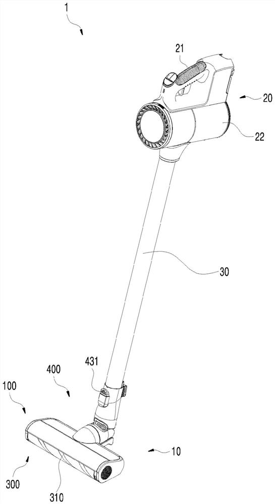
[0183] figure 1 It is a perspective view of the vacuum cleaner 1 which concerns on one Embodiment of this invention.
[0184] like figure 1 As shown, the vacuum cleaner 1 according to an embodiment of the present invention includes a body 20 and a suction nozzle 10 .
[0185] The suction nozzle 10 is connected to the body 20 through the extension tube 30 . The suction nozzle 10 may also be directly connected to the body 20 . The user can move the suction nozzle 10 placed on the ground back and forth while grasping the handle 21 formed on the main body 20 .
[0186] The main body 20 is a structure for forming a pressure difference of air. A blower is provided inside th...
PUM
 Abstract
Description
Claims
Application Information
 - R&D Engineer
- R&D Manager
- IP Professional
- Industry Leading Data Capabilities
- Powerful AI technology
- Patent DNA Extraction
Browse by: Latest US Patents, China's latest patents, Technical Efficacy Thesaurus, Application Domain, Technology Topic, Popular Technical Reports.
© 2024 PatSnap. All rights reserved.Legal|Privacy policy|Modern Slavery Act Transparency Statement|Sitemap|About US| Contact US: help@patsnap.com