
Motor capable of increasing positioning torque

A positioning torque and rotor technology, applied in the direction of magnetic circuit rotating parts, magnetic circuit shape/style/structure, magnetic circuit static parts, etc., can solve the problems of large space, high cost, complex structure, etc., and achieve equipment structure Simple, low noise, simple process effect

Pending Publication Date: 2022-07-12
深圳市德立威汽车部件有限公司
View PDF0 Cites 0 Cited by
  • Summary
  • Abstract
  • Description
  • Claims
  • Application Information

AI Technical Summary

Problems solved by technology

The advantage of this solution is to provide greater positioning torque, but the disadvantage is that the structure is complex, more space is required, and the cost is high.

Method used

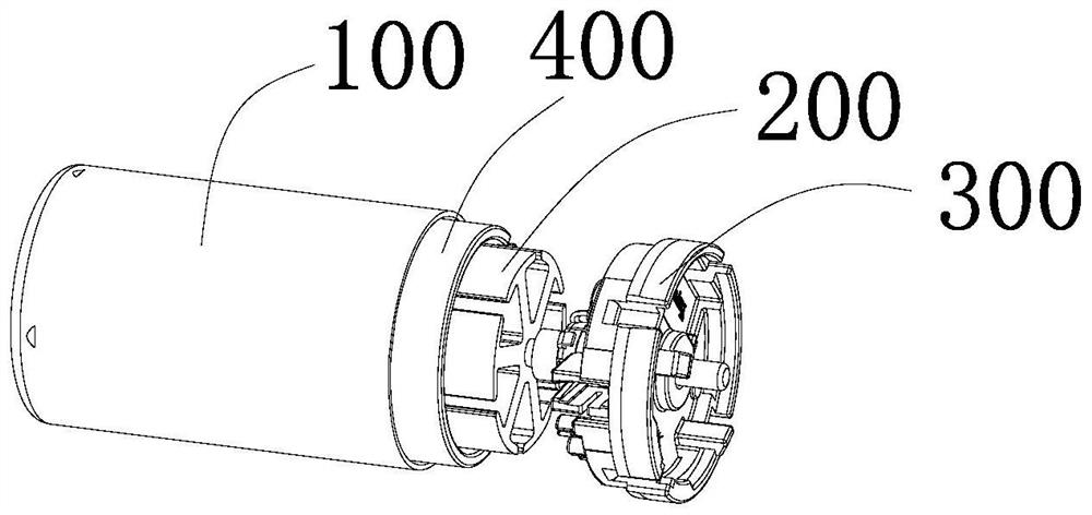
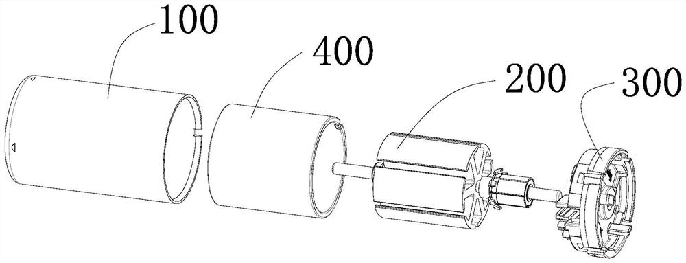
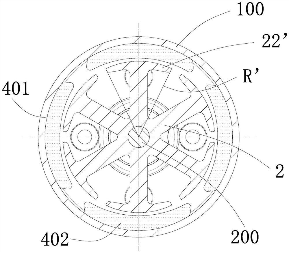

Image

  • Motor capable of increasing positioning torque
  • Motor capable of increasing positioning torque
  • Motor capable of increasing positioning torque

Examples


Embodiment 1

[0039] The connecting surface 23 is in the shape of an arc (the radius is denoted as R1), and the shape of the notch 221 is in the shape of an arc (the radius is denoted as R2).

Embodiment 2

[0041] The connecting surface 23 is in the shape of an arc (the radius is denoted as R1), and the shape of the notch 221 is in the shape of an arc (the radius is denoted as R2).

[0042] Compared with Embodiment 1, the difference between Embodiment 2 is that the radius of the arc-shaped connecting surface 23 is larger than that of the arc-shaped connecting surface 23 of Embodiment 1, and the side wall of the notch 221 and the pole piece 22 The outer edges are smoothly connected by circular arcs.

Embodiment 3

[0044] The engagement surface 23 is linear (the distance between the end of the linear engagement surface 23 away from the tooth portion 21 and the edge of the side close to the tooth portion 21 is denoted as C, and the linear engagement surface 23 is connected to the tooth portion 21 . The included angle of the center line is a0, and its value range is preferably 30°≤a0≤60°), and the shape of the notch 221 is a triangle (the maximum width of the notch 221 of the triangle is the distance between the two ends of the notch 221). distance H).

[0045] Specifically, the included angle between the tangent line where the connecting surface 23 and the inner edge of the pole piece 22 are connected and the connecting surface 23 is a1, and a1=0.6˜1.0a2.

[0046] Preferably, in the third embodiment, the shape of the notch 221 is an equilateral right triangle, and the right apex of the equilateral right triangle is located on the center line of the tooth portion 21, a0=45° (that is, the con...


PUM


Abstract

The invention provides a motor capable of increasing positioning torque. The motor capable of increasing the positioning torque comprises a punching sheet used for a stator or a rotor. The punching sheet comprises a base part, a plurality of tooth parts extending from the base part, and a plurality of pole shoes arranged at one ends of the tooth parts respectively. A notch is formed in the middle of the outer side of the pole shoe, and the outer side edges, close to the two ends, of the pole shoe are linear. Under the condition that a shell, a cover, a magnet and the like of the motor are not changed, the structure of the punching sheet used for the rotor or the stator is adjusted, the pole shoe is subjected to edge cutting and other treatment to form the linear outer side edge, and the notch is formed in the middle of the outer side of the pole shoe, so that the motor can rotate only by using larger torsion when the rotor shaft is rotated in a static state, and the rotating speed of the motor is improved. Therefore, the purpose of increasing the positioning torque is achieved.

Description

technical field [0001] The invention relates to the field of motors, in particular to a motor capable of increasing the detent torque. Background technique [0002] Electric machinery (commonly known as motor) refers to an electromagnetic device that realizes the conversion or transmission of electrical energy according to the law of electromagnetic induction. Its main function is to generate driving torque as a power source for electrical appliances or various machinery. Motors are widely used in electrical servo drives, transportation, household appliances, consumer electronics, automotive electrical equipment, national defense and aerospace and other fields. [0003] like figure 1 , figure 2 and image 3 As shown, the motor of the prior art includes a casing 100 , a rotor chip assembly 200 and a casing 300 , and a magnet 400 surrounding the rotor chip assembly 200 is provided inside the casing 100 . The magnet 400 includes N-pole magnetic tiles 401 and S-pole magneti...

Claims


Application Information

Patent Timeline
Patent Type & Authority Applications(China)
IPC IPC(8): H02K1/24H02K1/14
CPCH02K1/24H02K1/14H02K2213/03
Inventor 唐宪
Owner 深圳市德立威汽车部件有限公司
Learn More