Energy device exchange system for hydrogen energy moped

A technology of exchange system and hydrogen energy, applied in vehicle parts, transportation hydrogen technology, bicycle accessories, etc., can solve problems such as inconvenient exchange

Pending Publication Date: 2022-07-12
深圳市东氢能源科技有限公司
View PDF1 Cites 2 Cited by
  • Summary
  • Abstract
  • Description
  • Claims
  • Application Information

AI Technical Summary

Problems solved by technology

[0006] Aiming at the deficiencies of the prior art, the present invention provides an energy device exchanging system for a hydrogen-energy moped, which solves the problem of inconvenient exchange in a hydrogen-energy moped

Method used


Image

  • Energy device exchange system for hydrogen energy moped
  • Energy device exchange system for hydrogen energy moped
  • Energy device exchange system for hydrogen energy moped

Examples


Embodiment 1

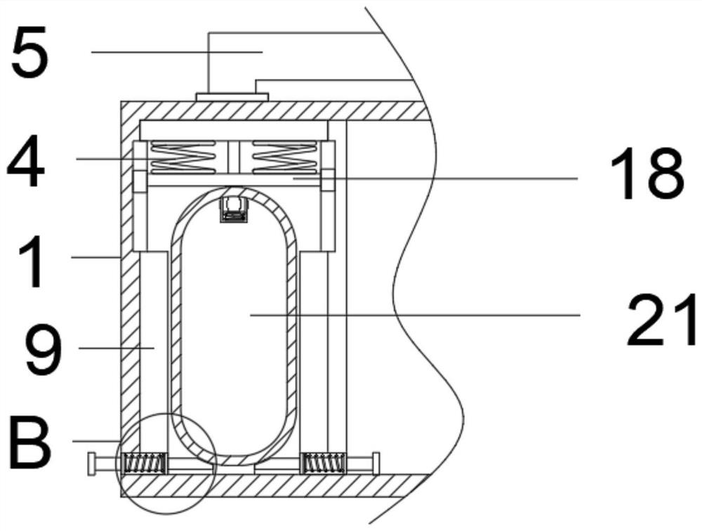
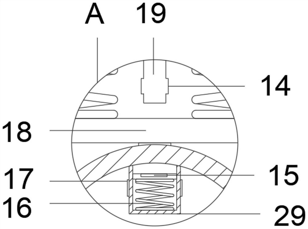
[0032] like Figure 1-6 As shown, the embodiment of the present invention provides an energy device exchange system for a hydrogen energy power-assisted vehicle, including an exchange device main body 1, and a first ventilation block 23, a second ventilation block 24, and a first ventilation block 23, a second ventilation block 24, and a first ventilation block 23, a second ventilation block 24, and a first ventilation block 23, a second ventilation block 24, and a first ventilation block 23 are fixedly connected to the top of the exchange device main body 1, respectively. Three ventilation blocks 28 , the first ventilation block 23 , the second ventilation block 24 and the third ventilation block 28 are fixedly connected with a chute 3 on both sides at one end of the inner side, and a slider 2 is slidably fitted inside the chute 3 . , through the sliding cooperation of the sliding slot 3 and the slider 2 to increase the stability, a support plate 18 is fixedly connected betwee...

Embodiment 2

[0035] By setting this structure, the sliding block 2 and the sliding groove 3, the sliding block 2 and the sliding groove 3 realize the stable effect of the support plate 18 during the elastic support of the first spring 4 to push and recover, and strengthen the movement of the support plate 18. At the same time, the sliding block 2 and the chute 3 are beneficial to the pushing of the hydrogen energy gas tank 21, reducing the friction force and reducing the pushing force.

[0036] The elastic support is achieved by the first spring 4 , which facilitates the insertion and pushes one end of the hydrogen energy gas tank 21 to push out of the fourth opening 27 for easy removal.

[0037] The replacement of multiple hydrogen energy gas tanks 21 is realized through the first ventilation block 23, the second ventilation block 24 and the third ventilation block 28, which is convenient to operate and has higher efficiency during use, and the cost of the main body 1 of the exchange device ...


PUM


Abstract

The energy device exchange system for the hydrogen energy moped comprises an exchange device body, the top end of the exchange device body is fixedly connected with a first air exchange block, a second air exchange block and a third air exchange block, and the two sides of one end of the interior of each of the first air exchange block, the second air exchange block and the third air exchange block are fixedly connected with sliding grooves; sliding grooves are formed in the exchange device body, sliding blocks are arranged in the sliding grooves in a sliding fit mode, a supporting plate is fixedly connected between the sliding blocks, a through hole is formed in the middle of the interior of the supporting plate, and first springs are fixedly connected to one side of the supporting plate and the two sides between the exchange device body. An air hydrogen energy gas tank outside the exchange device body is inserted into a fourth opening, a limiting block and an arc-shaped opening are recycled in a limiting stretching groove by pulling a pull block, the recycled hydrogen energy gas tank is inserted into a first ventilation block, and two-side limiting is performed through a limiting plate while insertion is performed, so that position deviation is prevented.

Description

technical field [0001] The invention relates to the technical field of hydrogen energy exchange devices, in particular to an energy device exchange system for a hydrogen energy power-assisted vehicle. Background technique [0002] The hydrogen energy battery vehicle refers to a "hydrogen internal combustion engine" driven by a device that generates electricity through the chemical reaction of hydrogen with oxygen, and only relies on the combustion of hydrogen. It has also appeared, such as BMW's hydrogen 7 series. The driving force of a hydrogen fuel cell vehicle comes from the electric motor on the vehicle, just like a pure electric vehicle, so a hydrogen fuel cell vehicle can be understood as an electric vehicle with its own hydrogen fuel generator. [0003] However, most of the hydrogen energy in the existing technology is used in automobiles. Compared with mopeds, hydrogen energy can also be used to realize the same principle of automobiles. The station is still insuffi...

Claims


Application Information

Patent Timeline
Patent Type & Authority Applications(China)
IPC IPC(8): B60L50/72B60L50/71B62J35/00B62M6/80
CPCB60L50/72B60L50/71B62J35/00B62M6/80B60L2200/46Y02T90/40
Inventor 赵璇王文帅
Owner 深圳市东氢能源科技有限公司
Why Eureka
Try Eureka