
Mobile vehicle-mounted camera for school bus

A mobile, camera technology, applied in image communication, vehicle components, TV, etc., can solve problems such as increasing difficulty, monitoring dead spots, and missing information, and achieve the effect of increasing the monitoring area

Pending Publication Date: 2022-07-08
CHONGQING COLLEGE OF ELECTRONICS ENG
View PDF0 Cites 0 Cited by
  • Summary
  • Abstract
  • Description
  • Claims
  • Application Information

AI Technical Summary

Problems solved by technology

[0002] Camera, also known as computer camera, computer eye, electronic eye, etc., is a video input device, which is widely used in video conferencing, telemedicine, vehicle driving record and real-time monitoring, etc. Due to the frequent occurrence of various adverse events, The requirements for monitoring are becoming more and more stringent. At present, there are basically real-time monitoring cameras installed on school buses. Although some school bus cameras can already rotate at a certain angle, sometimes there will still be monitoring dead angles, and most of the cameras They are all fixed in a place on the school bus for monitoring. If any camera is damaged, it will become a blind spot, resulting in the omission of important information. It has a great impact on the tracking of some events and increases the difficulty. In addition, some school buses are used to monitor the front of the car in real time. When students get on and off the bus at the front and at the door, cameras are installed at the front of the car and at the door, resulting in a large number of cameras on the entire school bus. The maintenance and maintenance of the cameras in the later stage will cause inconvenience and high maintenance costs.

Method used


Image

  • Mobile vehicle-mounted camera for school bus
  • Mobile vehicle-mounted camera for school bus
  • Mobile vehicle-mounted camera for school bus

Examples


Embodiment Construction

[0026] The technical solutions in the embodiments of the present invention will be clearly and completely described below with reference to the embodiments of the present invention. Obviously, the described embodiments are only a part of the embodiments of the present invention, rather than all the embodiments. Based on the embodiments of the present invention, all other embodiments obtained by those of ordinary skill in the art without creative work fall within the protection scope of the present invention.

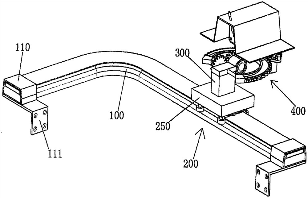
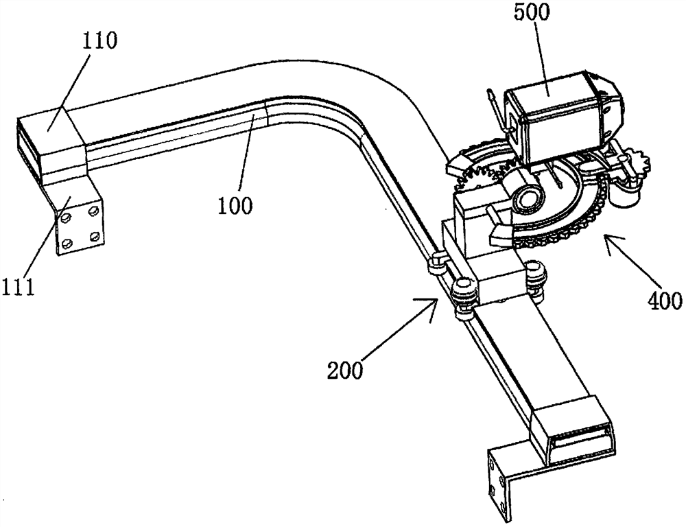
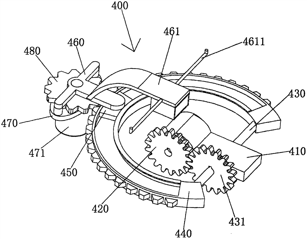
[0027] see Figure 1-6 As shown, a mobile vehicle-mounted camera for a school bus includes an L-shaped guide rail 100, a mobile device 200 is rollingly connected to the top of the L-shaped guide rail 100, a support column 300 is fixedly connected to the top surface of the mobile device 200, and the top surface of the support column 300 is connected A direction adjustment mechanism 400 is provided. The direction adjustment mechanism 400 includes a connection block 410. Th...


PUM


Abstract

The invention relates to the technical field of camera shooting equipment, in particular to a movable vehicle-mounted camera for a school bus, which comprises an L-shaped guide rail, the top of the L-shaped guide rail is in rolling connection with a moving device, the top surface of the moving device is fixedly connected with a supporting column, the top surface of the supporting column is provided with a direction adjusting mechanism, and the direction adjusting mechanism comprises a connecting block. A first motor fixedly sleeves one end of the connecting block, a first gear is fixedly connected to the output end of the first motor, a shaft rod is rotatably connected to the middle of the end, away from the first gear, of the connecting block, a second gear fixedly sleeves one end of the middle of the shaft rod, and the second gear and the first gear are in meshing transmission. According to the device, the first motor drives the first gear to rotate, the second motor drives the third gear to rotate, up-down and left-right rotation of the wireless camera is achieved, the wireless camera moves in the direction of the L-shaped guide rail, up-down and left-right rotation of the camera and linear movement of the camera are achieved, and the monitoring area is increased.

Description

technical field [0001] The invention relates to the technical field of camera equipment, in particular to a mobile vehicle-mounted camera for a school bus. Background technique [0002] Camera, also known as computer camera, computer eye, electronic eye, etc., is a video input device, which is widely used in video conferencing, telemedicine, vehicle driving records and real-time monitoring. Due to the frequent occurrence of various adverse events, The requirements for monitoring are getting stricter and stricter. At present, real-time monitoring cameras are basically installed on school buses. Although some school bus on-board cameras can already be rotated at a certain angle, sometimes there are still monitoring dead spots, and most cameras are They are all fixed in one place of the school bus for monitoring. If some cameras are damaged, they will become blind spots, resulting in missing important information. It has a great impact on the tracking of some events, which incr...

Claims


Application Information

Patent Timeline
IPC IPC(8): H04N5/225H04N7/18B60R11/04
CPCH04N7/18B60R11/04B60R2011/0021B60R2011/0085B60R2011/0092H04N23/54H04N23/50Y02E10/50
Inventor 胡云冰张春阳何学文刘洪君
Owner CHONGQING COLLEGE OF ELECTRONICS ENG
Learn More