Reciprocating motion mechanism

A technology of reciprocating motion mechanism and driving wheel, which is used in conveyor objects, transportation and packaging, furnaces, etc., can solve problems such as being vulnerable to impact, and achieve the effects of small impact force, stable extension and contraction rate, and simple structure.

Pending Publication Date: 2022-07-08
郑州科慧科技股份有限公司
View PDF9 Cites 0 Cited by
  • Summary
  • Abstract
  • Description
  • Claims
  • Application Information

AI Technical Summary

Problems solved by technology

[0003] The purpose of the present invention is to provide a reciprocating mechanism to solve the problem that materials are easily impacted during horizontal transplanting

Method used


Image

  • Reciprocating motion mechanism
  • Reciprocating motion mechanism
  • Reciprocating motion mechanism

Examples


Embodiment 1

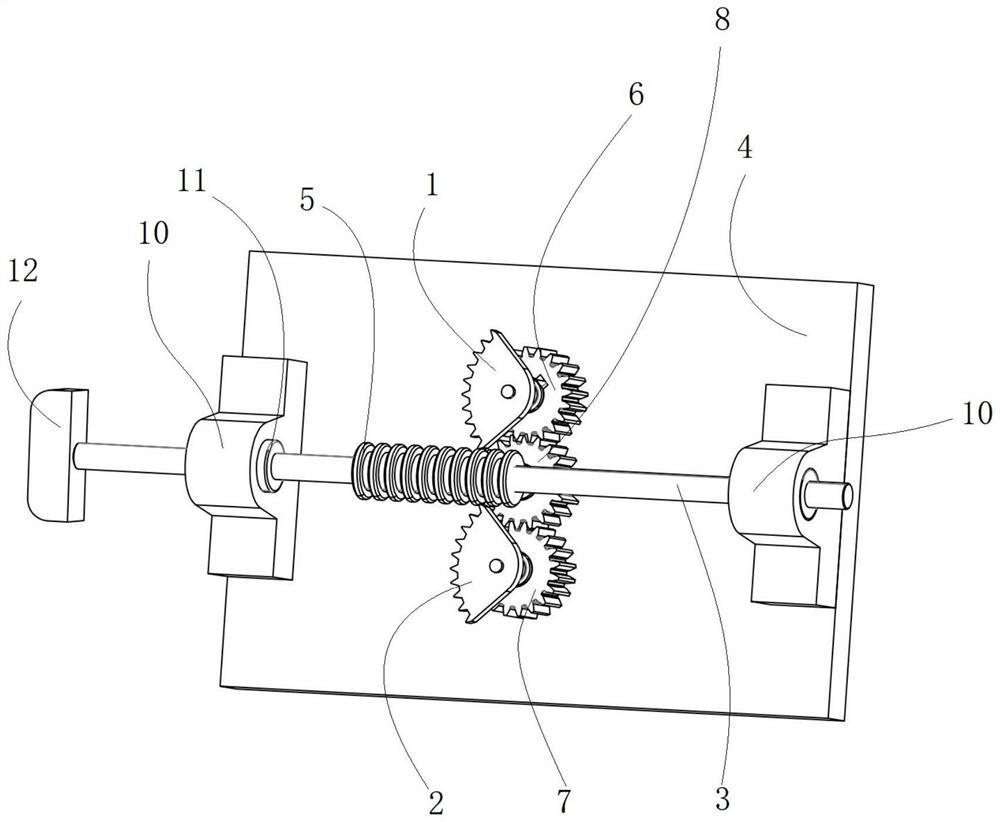
[0025] figure 1 As shown, the reciprocating mechanism includes a first sector tooth 1, a second sector tooth 2, a telescopic rod 3, the first sector tooth 1 and the second sector tooth 2 are arranged at intervals, and the telescopic rod 3 is arranged on the first sector tooth 1 and the second sector tooth 2. Between the two sector teeth 2, the rod body of the telescopic rod 3 is provided with a meshing part along the length direction of the telescopic rod 3, the rotation directions of the first sector tooth 1 and the second sector tooth 2 are the same, It is used to alternately engage with the meshing parts on the telescopic rod 3 to drive the telescopic rod 3 to reciprocate, and the telescopic rod 3 is driven to move horizontally by the rotation of the sector teeth, and the first fan teeth 1 and the second fan teeth 2 cooperate to realize the telescopic rod. 3 Linear and uniform reciprocating motion to avoid impact on the material when pushing the material.

[0026] Specific...


PUM


Abstract

The reciprocating motion mechanism comprises a first sector gear, a second sector gear and a telescopic rod, the first sector gear and the second sector gear are arranged at intervals, the telescopic rod is arranged between the first sector gear and the second sector gear, a meshing part is arranged on a rod body of the telescopic rod in the length direction of the telescopic rod, and the rotating directions of the first sector gear and the second sector gear are consistent. The first sector gear and the second sector gear are used for being alternately meshed with meshing parts on the telescopic rod so as to drive the telescopic rod to reciprocate. Compared with an existing air cylinder pushing mode, the material pushing device is simple in structure, low in cost, stable in extension and contraction rate of the telescopic rod, small in impact force and capable of effectively protecting materials from being impacted.

Description

technical field [0001] The invention relates to the technical field of material transplanting, in particular to a reciprocating motion mechanism. Background technique [0002] In the case of conveying the material to the next station during the conveying line operation, such as in the palletizing process, after the material is taken off the conveying line, the material needs to be horizontally transplanted to the waiting area for palletizing. At present, most of the transplanted materials use cylinders. The expansion and contraction of the cylinder pushes the material to move horizontally, but the expansion and contraction of the cylinder is fast and has a certain impact. It is not suitable for pushing materials that are light, brittle and easily deformed by impact. SUMMARY OF THE INVENTION [0003] The purpose of the present invention is to provide a reciprocating motion mechanism to solve the problem of being easily impacted in horizontal transplanting of materials. [...

Claims


Application Information

Patent Timeline
Patent Type & Authority Applications(China)
IPC IPC(8): B65G47/82B65G49/05
CPCB65G47/82B65G49/05
Inventor 张震王允胡一帆尹传闯
Owner 郑州科慧科技股份有限公司
Why Eureka
Try Eureka