


Quick Research
Generate reliable direction feasibility study reports for your R&D in just a few steps.

Technical Q&A
Discover and master advanced knowledge NOW. Basics, ideas, possibilities, all at once.

Find Solutions
As an expert in R&D theories, this can generate solutions to your technical problems instantly.

Evaluate Feasibility
Analyze your overall solution with one click, know your potential R&D risks in advance.

Monitor Landscape
Get weekly tech updates, stay abreast of the latest tech innovations and key insights.
Gynecological cervical cancer screening instrument
A technology of cervical cancer screening instrument, which is applied in the field of gynecology, can solve the problems of patients' physiological discomfort, affect the diagnosis result, and cannot guarantee the accuracy of sampling, so as to achieve the effect of ensuring accuracy
- Summary
- Abstract
- Description
- Claims
- Application Information
AI Technical Summary
Problems solved by technology
Method used
Image


Examples
specific Embodiment approach
[0044] As a specific embodiment of the present invention, the sampling assembly includes:
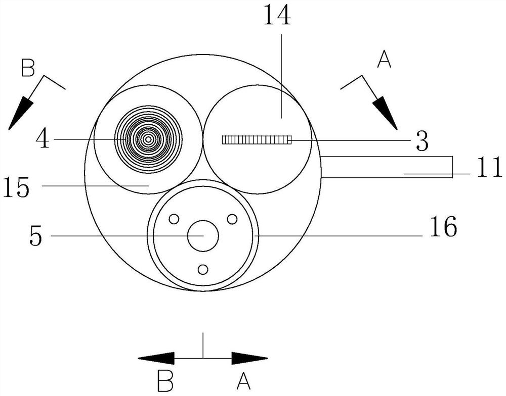
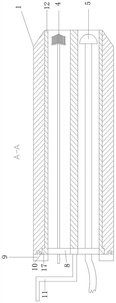
[0045] Cylinder 12, the cylinder 12 is located inside the casing 1, and the interior of the cylinder 12 is provided with two tangent No. 1 through holes 16, No. 2 through holes 14 and No. 3 through holes 15 around the circumference;
[0046] The camera head 5, the camera head 5 is located in the No. 1 through hole 16 inside the cylinder 12, and the line fixedly connected at the rear of the camera head 5 extends to the outer body 2 of the cylinder 12 through the three-hole turntable 8;
[0047] HPV brush 3: the brush is located in the third through hole 15 inside the cylinder 12, and the tail of the brush extends to the outside of the cylinder 12 through the three-hole turntable 8;
[0048] TCT brush 4: The TCT brush 4 is located in the third through hole 15 inside the cylinder 12, and the tail of the TCT brush 4 extends to the outside of the cylinder 12 through the three-hole turntable ...
Embodiment approach
[0062] As a specific embodiment of the present invention, the camera 5 is a hemispherical camera.
[0063] The camera 5 of the present invention is a hemispherical camera for the scope of observation. Compared with the ordinary single-directional camera, the hemispherical camera can perform multi-directional observation, which is more conducive to medical staff to observe the internal physical condition of the patient, and reduces the need for observation. The single direction brings the limitations of the observation position, which is more conducive to the screening work.
[0064] As a specific embodiment of the present invention, a disinfection tank 7 is provided above the display 13 .
[0065] In the present invention, for the safety of the patient and to prevent the present invention from contacting bacteria in the air, a disinfection tank 7 is provided on the upper side of the display 13. Whenever the sampling assembly starts to work, it will be taken out through the dis...
PUM
 Abstract
Description
Claims
Application Information
 - R&D Engineer
- R&D Manager
- IP Professional
- Industry Leading Data Capabilities
- Powerful AI technology
- Patent DNA Extraction
Browse by: Latest US Patents, China's latest patents, Technical Efficacy Thesaurus, Application Domain, Technology Topic, Popular Technical Reports.
© 2024 PatSnap. All rights reserved.Legal|Privacy policy|Modern Slavery Act Transparency Statement|Sitemap|About US| Contact US: help@patsnap.com