Aircraft vibration superposition fatigue strength testing system and low-rigidity load applying method thereof
A fatigue strength and testing system technology, applied in the field of aircraft testing, can solve the problems of fatigue load loading that cannot be quickly changed, complex technical paths, and high costs, and achieve high convenience and feasibility, broad application prospects, and rapid weight gain. Effect
- Summary
- Abstract
- Description
- Claims
- Application Information
AI Technical Summary
Problems solved by technology
Method used
Image
Examples
Embodiment 1
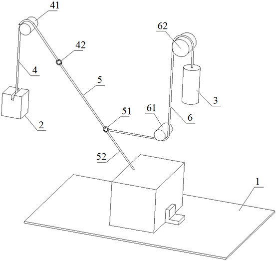
[0040] like figure 1 As shown, the aircraft vibration superposition fatigue strength test system includes a vibration table 1 for placing aircraft specimens, a main weight 2 for applying static load, and an actuator 3 for adjusting the static load. The actuator 3 is Commercially available in the aerospace industry as a propeller;
[0041] The top of the main weight 2 is provided with a first wire rope 4, and the end of the first wire rope 4 is provided with a first steel ring 42 after passing around the first certain pulley 41. The first steel ring 42 is connected with a rubber rope 5, and the rubber rope 5 is another. One end is connected with a second steel ring 51, the second steel ring 51 is connected with the aircraft test piece placed above the vibration table 1 through a second steel wire rope 52, and the second steel ring 51 is also connected with the actuator through a third steel wire rope 6. 3 The top is connected, the third wire rope 6 goes around the second fixed...
Embodiment 2
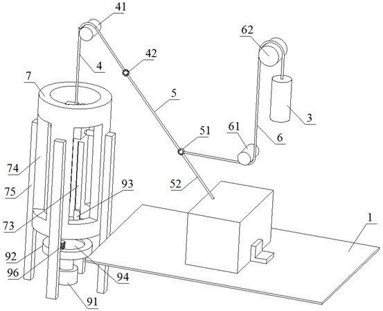
[0043] like figure 2 As shown, the aircraft vibration superposition fatigue strength test system includes a shaking table 1 for placing aircraft specimens, a main weight 2 for applying static load, and an actuator 3 for adjusting static load;
[0044] The top of the main weight 2 is provided with a first wire rope 4, and the end of the first wire rope 4 is provided with a first steel ring 42 after passing around the first fixed pulley 41. The first steel ring 42 is connected with three rubber ropes 5, and the rubber rope 5 is another. One end is connected with a second steel ring 51, the second steel ring 51 is connected with the aircraft test piece placed above the vibration table 1 through a second steel wire rope 52, and the second steel ring 51 is also connected with the actuator through a third steel wire rope 6. 3 The top is connected, the third wire rope 6 goes around the second fixed pulley 61 and the third fixed pulley 62 in turn, the bottom of the second fixed pulle...
Embodiment 3
[0048] This embodiment is based on the low-rigidity load application method of the aircraft vibration superimposed fatigue strength test system in Embodiment 1, such as Figure 7 shown, including the following steps:
[0049] S1. Preparation:
[0050] S1-1: Determine the application direction of the static load, connect the first wire rope 4 to the aircraft specimen, and the first wire rope 4 extends along the static load application direction;
[0051] S1-2: Determine the applied amount of static load, adjust the weight of the main weight 2 according to the applied amount, and select a rubber rope 5 with appropriate stiffness. When the entire weight of the main weight 2 acts on the rubber rope 5, the rubber rope 5 The elongation is 130% of the original length;
[0052] S1-3: Determine the applied frequency of the static load, and adjust the actuating force, loading frequency and displacement of the actuator 3 according to the applied frequency;
[0053] S2. Static load app...
PUM
 Abstract
Description
Claims
Application Information
 - R&D
- Intellectual Property
- Life Sciences
- Materials
- Tech Scout
- Unparalleled Data Quality
- Higher Quality Content
- 60% Fewer Hallucinations
Browse by: Latest US Patents, China's latest patents, Technical Efficacy Thesaurus, Application Domain, Technology Topic, Popular Technical Reports.
© 2025 PatSnap. All rights reserved.Legal|Privacy policy|Modern Slavery Act Transparency Statement|Sitemap|About US| Contact US: help@patsnap.com


