Intelligent jacquard piezoelectric ceramic positive and negative double-voltage driving circuit and warp knitting machine
A positive and negative dual voltage, drive circuit technology, applied in the field of warp knitting machines, can solve problems such as complex circuit structures, achieve the effects of reducing production costs, improving stability, and reducing overall machine costs
- Summary
- Abstract
- Description
- Claims
- Application Information
AI Technical Summary
Problems solved by technology
Method used
Image
Examples
Embodiment 1
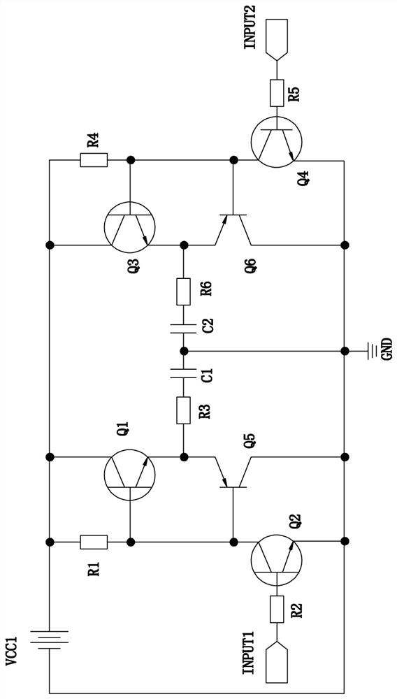
[0020] Embodiment 1, a smart jacquard piezoelectric ceramic positive and negative dual-voltage drive circuit and warp knitting machine, the warp knitting machine includes at least one jacquard device, at least one industrial computer, at least one jacquard bar controller, at least one proximity A switch and at least one jacquard bar driver for driving the jacquard bar jacquard guide yarn, the jacquard device includes at least one bar bed and at least one jacquard bar installed on the bar bed, and the jacquard bar controller There is a 32-bit ARM embedded processor inside.
[0021] The industrial computer is a common industrial control computer with built-in corresponding Jacquard comb driver software.
[0022] The industrial computer is provided with a first data communication interface capable of data communication with the Jacquard bar controller and a second data communication interface used for reading the Jacquard craft file.
[0023] The proximity switch is used to dete...
Embodiment 2
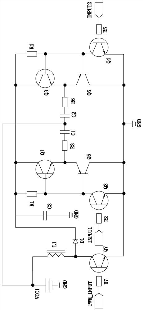
[0035] Embodiment 2, refer to figure 2 The difference between the second embodiment and the first embodiment is that the driving circuit also includes a capacitor C3, a diode D1, an inductance coil L1, a transistor Q7 and a resistor R7, and one end of the resistor R1 and the cathode of the diode D1 are connected in parallel with the capacitor C3. One end, the other end of the capacitor C3 is grounded, one end of the inductor coil L1 is connected in parallel with the positive electrode of the power supply VCC1, the other end of the inductor coil L1 and the collector of the transistor Q7 are connected in parallel with the anode of the diode D1, and the emitter of the transistor Q7 is connected in parallel with the anode of the transistor Q2. Emitter, one end of the resistor R7 is connected to the base of the transistor Q7, the other end of the resistor R7 is connected to an input terminal PWM_INPUT, the negative pole of the power supply VCC1 is grounded, the input terminal PWM_I...
PUM
 Abstract
Description
Claims
Application Information
 - Generate Ideas
- Intellectual Property
- Life Sciences
- Materials
- Tech Scout
- Unparalleled Data Quality
- Higher Quality Content
- 60% Fewer Hallucinations
Browse by: Latest US Patents, China's latest patents, Technical Efficacy Thesaurus, Application Domain, Technology Topic, Popular Technical Reports.
© 2025 PatSnap. All rights reserved.Legal|Privacy policy|Modern Slavery Act Transparency Statement|Sitemap|About US| Contact US: help@patsnap.com


