
Camera module appearance detection device and control method

A camera module, appearance inspection technology, applied in measuring devices, optical testing flaws/defects, instruments, etc., can solve the problems of quality problems, camera damage, cracks, etc. of finished products, so as to achieve consistent production quality and accurate computer judgment. , the effect of clear image

Pending Publication Date: 2022-07-01
SHENZHEN OKOWA PRECISION AUTOMATION
View PDF0 Cites 1 Cited by
  • Summary
  • Abstract
  • Description
  • Claims
  • Application Information

AI Technical Summary

Problems solved by technology

[0002] The production of the camera module needs to go through multiple processes such as baking FPC, dispensing glue, pasting the wafer, covering the lens holder, and baking. Any problem in any process may cause quality problems in the final product. Therefore, after the camera module production is completed Finally, the production line will inspect the finished product in all aspects to find defective products in time. Among them, the appearance inspection of the camera module is a very important link. Its appearance defects will lead to hidden dangers in the quality of the entire product, such as cracks on the appearance. Stress can be generated in the
The appearance detection of the existing camera module can be detected by a computer, but the appearance image of the camera module needs to be uploaded to the computer and then inspected. It is impossible to fully realize the automatic shooting of the six sides of the camera module, and manual participation is required. Not only Time-consuming and labor-intensive, and non-standard, it is prone to blurred images, and the computer is not easy to judge, resulting in uneven quality of the camera module after the inspection

Method used


Image

  • Camera module appearance detection device and control method
  • Camera module appearance detection device and control method
  • Camera module appearance detection device and control method

Examples


Embodiment Construction

[0037] The principles and features of the present invention are described below, and the examples are only used to explain the present invention, but not to limit the scope of the present invention.

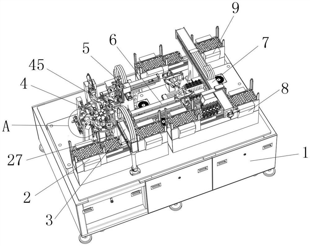
[0038] In a specific embodiment, as Figure 1-7 As shown, a camera module appearance detection device includes a feeding mechanism 2, a first reclaiming mechanism 3, a rotating mechanism 4, a second reclaiming mechanism 5, a linear mechanism 6, a third Material mechanism 7, intact product receiving mechanism 8 and defective product receiving mechanism 9.

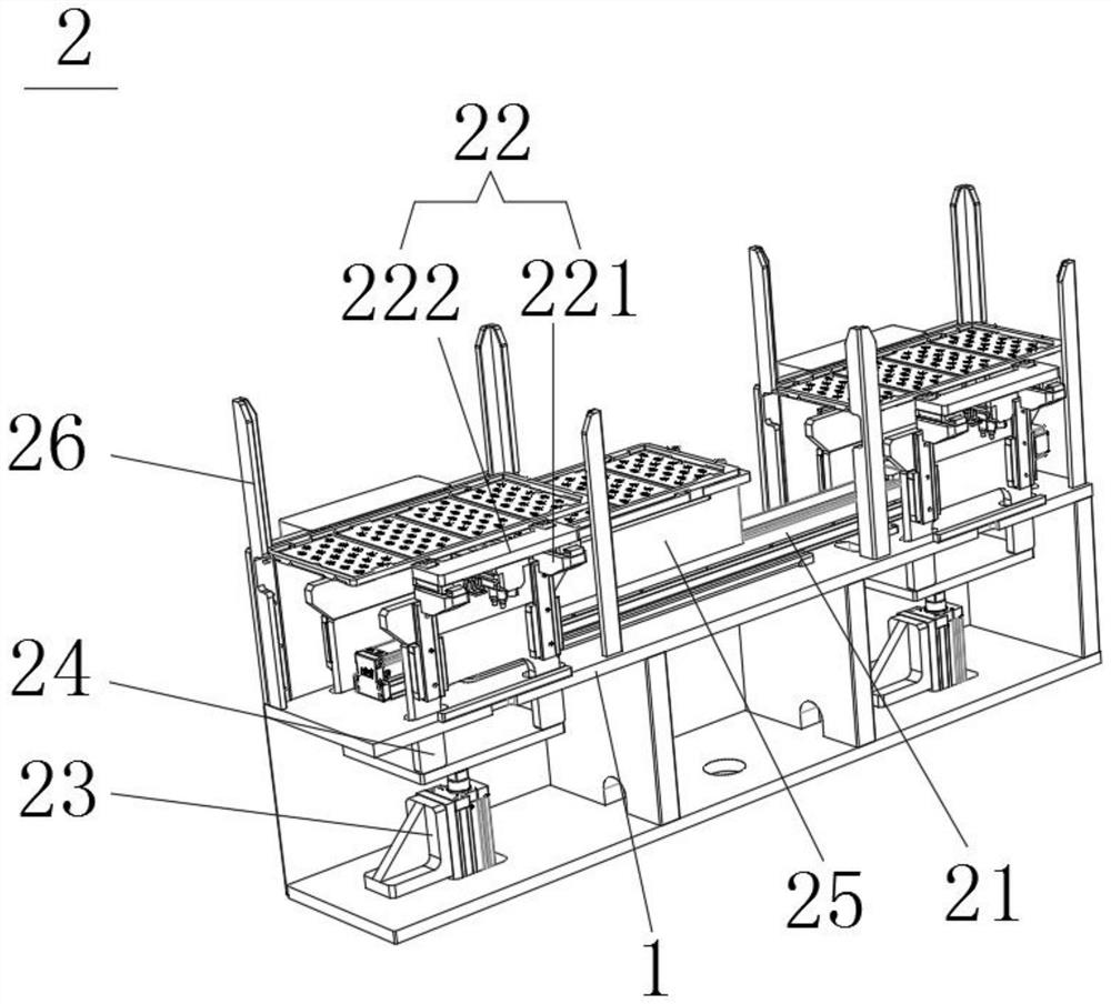
[0039] like figure 2 and image 3As shown, the feeding mechanism 2 includes a first guide rail 21 fixedly arranged on the installation table 1, two clamps 22 and an electric push rod 23 in number, and a bearing is fixed on the driving end of the first guide rail 21 seat 25, the top of the bearing seat 25 is provided with a limit protruding strip 251, and the bottom of the tray is provided with a corresponding slot 253, that...


PUM


Abstract

The invention provides a camera module appearance detection device which comprises a feeding mechanism, a first material taking mechanism, a rotating mechanism, a second material taking mechanism, a linear mechanism, a third material taking mechanism, a complete product receiving mechanism and a defective product receiving mechanism which are fixedly arranged, and a first bottom surface detection module is arranged between the rotating mechanism and the feeding mechanism; the first material taking mechanism takes the camera module from the feeding mechanism and conveys the camera module to the rotating mechanism, the bottom face of the camera module is detected through the first bottom face detection module in the conveying process, and a top face detection module is arranged at the top of the rotating mechanism and used for detecting the top face of the camera module. According to the camera module appearance detection device, feeding and discharging are conducted through machinery, the camera module is moved to the detection area of the appearance detection module for face-by-face detection, so that appearance detection of the camera module forms a complete procedure, manual participation is not needed, time and labor are saved, manual subjective judgment is avoided, and the production quality of the camera module is kept consistent.

Description

technical field [0001] The invention relates to the technical field of component detection, in particular to a camera module appearance detection device and a control method. Background technique [0002] The production of camera modules needs to go through multiple processes such as baking FPC, dispensing, pasting wafers, covering lens holders, baking, etc. Problems in any process may lead to quality problems in the final product, so the camera module is completed after production. After that, the production line will inspect all aspects of the finished product and find defective products in time. Among them, the appearance inspection of the camera module is a very important link. stress can occur in the camera, causing damage to the camera. The appearance inspection of the existing camera module can be detected by a computer, but the appearance image of the camera module needs to be uploaded to the computer and then detected, which cannot fully realize the automatic shoot...

Claims


Application Information

Patent Timeline
Patent Type & Authority Applications(China)
IPC IPC(8): G01N21/88G01N21/01B07C5/02B07C5/34B07C5/36
CPCG01N21/88G01N21/01B07C5/02B07C5/34B07C5/362
Inventor 刘立聪
Owner SHENZHEN OKOWA PRECISION AUTOMATION
Learn More