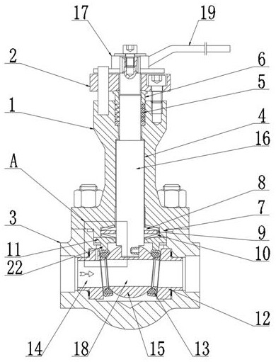
Top-mounted ultralow-temperature floating ball valve
A floating ball valve, ultra-low temperature technology, applied in the direction of valve details, valve device, valve shell structure, etc., can solve the problems of difficult leakage to meet the standard requirements, reduced sealing performance, leakage, etc., to achieve simple structure, improved sealing performance, and guaranteed sealing sexual effect
- Summary
- Abstract
- Description
- Claims
- Application Information
AI Technical Summary
Problems solved by technology
Method used
Image

Examples
Embodiment Construction
[0027] The technical solutions of the present invention will be clearly and completely described below with reference to the accompanying drawings in the embodiments of the present invention. Obviously, the described embodiments are only a part of the embodiments of the present invention, not all of the embodiments. Based on the embodiments of the present invention, all other embodiments obtained by those of ordinary skill in the art without creative work fall within the protection scope of the present invention;
[0028] It should be noted that, in the description of the present invention, it should be noted that the terms "inner", "outer", "upper", "lower", "both sides", "one end", "the other end" and "left" The orientation or positional relationship indicated by "right" and the like is based on the orientation or positional relationship shown in the drawings, and is only for the convenience of describing the present invention and simplifying the description, rather than indi...
PUM
 Abstract
Description
Claims
Application Information
 - Generate Ideas
- Intellectual Property
- Life Sciences
- Materials
- Tech Scout
- Unparalleled Data Quality
- Higher Quality Content
- 60% Fewer Hallucinations
Browse by: Latest US Patents, China's latest patents, Technical Efficacy Thesaurus, Application Domain, Technology Topic, Popular Technical Reports.
© 2025 PatSnap. All rights reserved.Legal|Privacy policy|Modern Slavery Act Transparency Statement|Sitemap|About US| Contact US: help@patsnap.com