
Supercharging device for chemical process

A pressurization device and process technology, applied to the parts of the pumping device used for elastic fluid, the cleaning method using gas flow, the cleaning method and the appliance, etc., which can solve the problem of effectively removing and cooling the surface heat of the booster pump The structure is difficult to dissipate heat, consume a lot of time and energy, etc., to reduce the process of manual cleaning, increase the scope of cleaning, and increase efficiency

Active Publication Date: 2022-07-01
BENGBU AIPU COMPRESSOR MACHINERY
View PDF6 Cites 0 Cited by
  • Summary
  • Abstract
  • Description
  • Claims
  • Application Information

AI Technical Summary

Problems solved by technology

[0002] When the existing supercharging equipment is placed for a long time, a large amount of dust will adhere to its surface. It is inconvenient to clean the dead corners manually, which requires a lot of time and energy. It is difficult to clean a small part of the area, and it is difficult to clean the entire booster equipment. At the same time, after the booster equipment has been in operation for a long time, the heat on the surface of the booster pump is difficult to be effectively removed, and the existing cooling structure is difficult to achieve efficient cooling. heat radiation

Method used


Image

  • Supercharging device for chemical process
  • Supercharging device for chemical process
  • Supercharging device for chemical process

Examples


Embodiment Construction

[0029] The technical solutions of the present invention will be clearly and completely described below with reference to the embodiments. Obviously, the described embodiments are only a part of the embodiments of the present invention, rather than all the embodiments. Based on the embodiments of the present invention, all other embodiments obtained by those of ordinary skill in the art without creative efforts shall fall within the protection scope of the present invention.

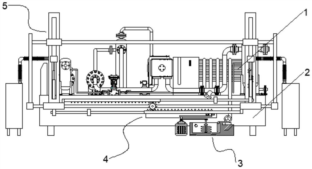
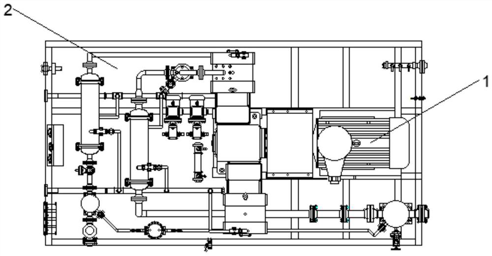
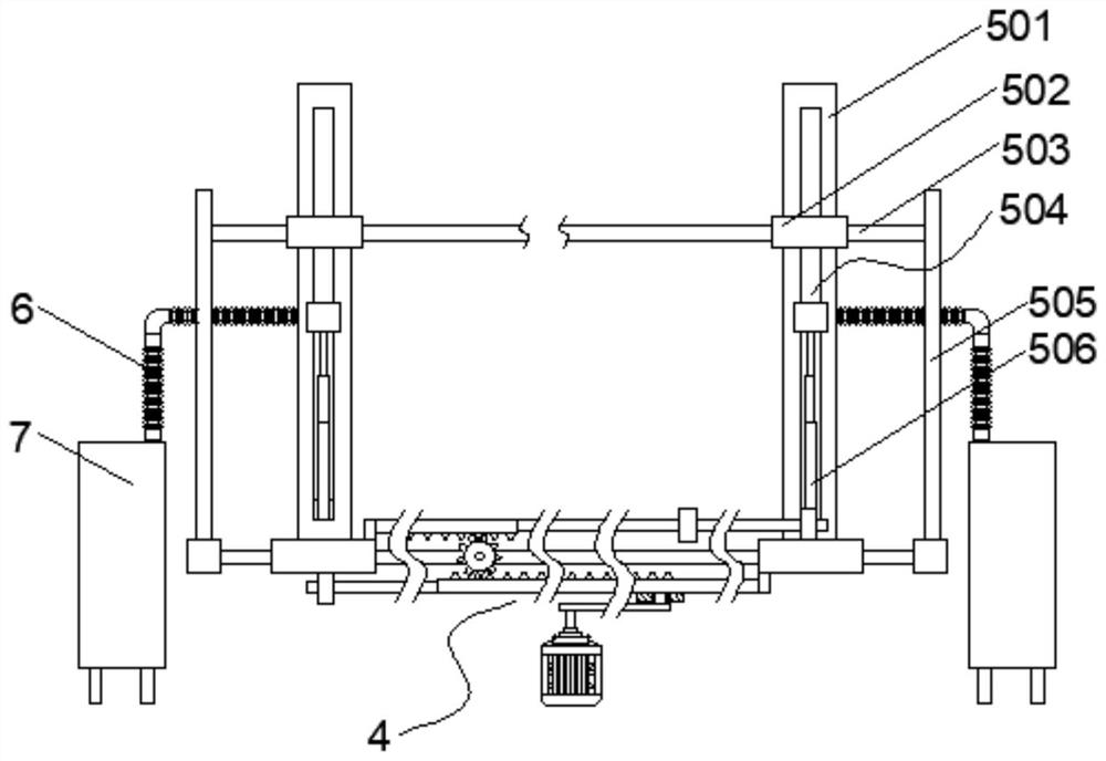
[0030] see figure 1 and figure 2 As shown, the pressurizing device for chemical process includes a base 2, the top of the base 2 is provided with a pressurizing device 1, the front of the base 2 is provided with a transmission mechanism 4, and the two sides of the transmission mechanism 4 are symmetrically provided with a pressurization device for cleaning The cleaning mechanism 5 of the dust on the surface of the equipment 1, and the bottom of the base 2 is provided with a water cooling mechanism 3 for...


PUM


Abstract

The supercharging device for the chemical process comprises a base, supercharging equipment is arranged at the top of the base, a transmission mechanism is arranged on the front face of the base, and cleaning mechanisms used for cleaning dust on the surface of the supercharging equipment are symmetrically arranged on the two sides of the transmission mechanism. The cleaning mechanism comprises a moving mechanism located over the supercharging equipment, a moving plate is arranged on the front face of the moving mechanism, a first sliding groove is formed in the moving plate, an electric push rod is fixedly installed at the bottom of the inner wall of the first sliding groove, and the horizontal height of a first rack is adjusted through stretching and retracting of the electric push rod; the dust collection device is simple in structure and easy to fit the structure of the supercharging equipment, the horizontal position of the dust collection head is conveniently controlled by moving the movable shell on the first rack, the longitudinal angle is adjusted through the dust collection head, dead corners of the structure of the supercharging equipment are conveniently cleaned, the cleaning efficiency is improved, and meanwhile the influence on the structure of the supercharging equipment during manual cleaning is reduced.

Description

technical field [0001] The invention relates to the technical field of pressurizing devices, in particular to a pressurizing device used in chemical processes. Background technique [0002] When the existing pressurized equipment is placed for a long time, a large amount of dust will adhere to its surface, which is inconvenient to manually clean the dead corners, and requires a lot of time and energy. It is difficult to completely clean the entire booster equipment after cleaning a small part of the area. At the same time, after the booster equipment has been used for a long time, the heat on the surface of the booster pump is difficult to effectively remove, and the existing cooling structure is difficult to achieve high efficiency. heat radiation. SUMMARY OF THE INVENTION [0003] The technical problems solved by this solution are: [0004] (1) How to set the cleaning mechanism and adjust the level of the first rack through the electric push rod, so as to easily fit th...

Claims


Application Information

Patent Timeline
Patent Type & Authority Applications(China)
IPC IPC(8): F04D29/58F04D29/70B08B5/04B08B13/00
CPCF04D29/586F04D29/708B08B5/04B08B13/00
Inventor 王淮北刘军
Owner BENGBU AIPU COMPRESSOR MACHINERY
Learn More