Novel safety protection device for water conservancy construction

A safety protection device and a new technology, applied in the field of new safety protection devices, can solve the problems of inconvenient device moisture-proof and anti-rust treatment, inconvenient lifting device structure anti-impact effect, inconvenient construction equipment adaptability and fixation, etc., to achieve lifting and rust removal Moisture-proof effect, effect of improving activity stability, effect of improving information warning effect

Pending Publication Date: 2022-07-01
陈奎娟
View PDF12 Cites 0 Cited by
  • Summary
  • Abstract
  • Description
  • Claims
  • Application Information

AI Technical Summary

Problems solved by technology

[0005] In order to make up for the shortcomings of the existing technology, it is not convenient to carry out adaptive fixing operation on the construction equipment, it is not convenient to carry out moisture-proof and anti-rust treatment on the device, and it is not convenient to improve the anti-impact effect of the device structure

Method used


Image

  • Novel safety protection device for water conservancy construction
  • Novel safety protection device for water conservancy construction
  • Novel safety protection device for water conservancy construction

Examples


Embodiment 1

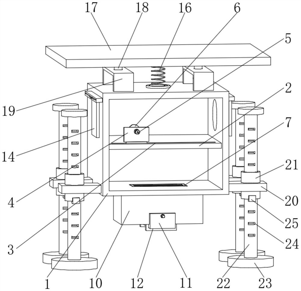
[0029] see figure 1 , image 3 and Figure 4 As shown, a new type of safety protection device for water conservancy construction includes a fixed frame 1 and a side plate 20, the inner side of the fixed frame 1 is provided with an isolation plate 2, and the inner side of the isolation plate 2 is provided with a sliding groove 3, and the sliding groove 3 The inner side is provided with a threaded plate 4, and the inner side of the threaded plate 4 is penetrated with a threaded rod 5, and the end of the threaded rod 5 is provided with an abutting disc 6, the bottom of the isolation plate 2 is provided with a drying box 7, and the drying box 7 is provided with a drying box 7. The end is provided with a connecting rod 8, the outer wall of the drying box 7 is provided with a sealing cover 9, the outer side of the drying box 7 is provided with a connecting box 10, and the bottom of the drying box 7 is provided with a limiting plate 11, the outer side of the limiting plate 11 is pro...

Embodiment 2

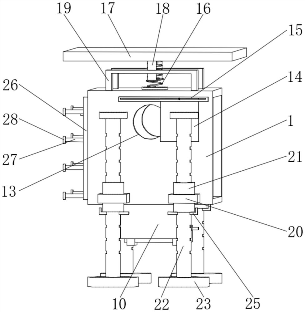
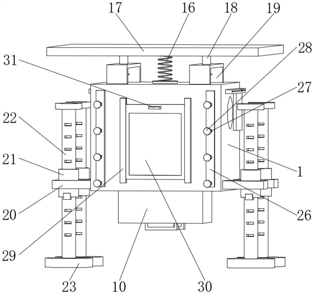
[0035] see Figure 1 to Figure 5As shown in the comparison example 1, as another embodiment of the present invention, the side plate 20 is arranged at the end of the fixed frame 1, and the inner side of the side plate 20 is provided with a hollow sleeve 21, and the inner side of the hollow sleeve 21 is provided with a support Column 22, and the end of the support column 22 is provided with support feet 23, the inner side of the support column 22 is provided with a positioning hole 24, and the inner side of the positioning hole 24 is provided with a positioning plate 25, and the back of the fixed frame 1 is provided with a connecting plate 26, And the outer wall of the connecting plate 26 is provided with a hanging rod 27, and the end of the hanging rod 27 is provided with an end head 28, the side of the connecting plate 26 is provided with a limit frame 29, and the inner side of the limit frame 29 is provided with a warning board 30, and the end of the warning plate 30 is prov...


PUM


Abstract

The invention belongs to the field of safety protection devices, and particularly relates to a novel safety protection device for water conservancy construction, the novel safety protection device comprises a fixing frame and a side plate, the inner side of the fixing frame is provided with an isolation plate, the inner side of the isolation plate is provided with a sliding groove, the inner side of the sliding groove is provided with a threaded plate, and a threaded rod penetrates through the inner side of the threaded plate; the bottom of the isolation plate is provided with a drying box, the end of the drying box is provided with a connecting rod, the outer wall of the drying box is provided with a sealing cover plate, the outer side of the drying box is provided with a connecting box, the bottom of the drying box is provided with a limiting plate, and the outer side of the limiting plate is provided with a fixing sleeve. A heat dissipation groove is formed in the side of the fixed frame, and a movable cover plate is arranged on the side of the heat dissipation groove; construction equipment can be conveniently subjected to adaptive fixing operation, the device can be conveniently subjected to damp-proof and rust-proof treatment, and the anti-impact effect of the device structure can be conveniently improved.

Description

technical field [0001] The invention relates to the field of safety protection devices, in particular to a new type of safety protection device for water conservancy construction. Background technique [0002] Equipment safety protection facilities include protective cover, protective screen, load limiter, travel limiter, braking, speed limit, lightning protection, moisture-proof, sun-proof, anti-freeze, anti-corrosion, anti-leakage and other facilities, safety locking facilities for transmission equipment, electrical appliances Overload protection facilities, electrostatic grounding facilities, and safety facilities refer to the devices (equipment) and measures provided by enterprises (units) to control dangerous and harmful factors within a safe range, and to reduce, prevent and eliminate hazards during production and operation activities. measure. [0003] The traditional safety protection device has the problems that it is inconvenient to carry out the adaptive fixing o...

Claims


Application Information

Patent Timeline
Patent Type & Authority Applications(China)
IPC IPC(8): E02B1/00F26B9/06B25H3/00
CPCE02B1/00F26B9/06B25H3/00
Inventor 陈奎娟魏福生赵晓辉王卫喜沈钰
Owner 陈奎娟
Why Eureka
Try Eureka