
Stacking machine

A technology of stacker and synchronous belt, applied in the field of stacker, can solve the problems such as insufficient conveying distance of stacker, inability to deliver to a predetermined location, slippage, etc., to achieve convenient operation, improve sliding accuracy, and improve meshing stability sexual effect

Pending Publication Date: 2022-07-01
平湖市开浦机电集成有限公司
View PDF0 Cites 1 Cited by
  • Summary
  • Abstract
  • Description
  • Claims
  • Application Information

AI Technical Summary

Problems solved by technology

[0003] During the use of the existing stacker, the stacker directly slides on the slide rail, and the roller is directly driven by the motor, and the roller slides on the slide rail. During the use of this driving method, the roller is easy to get between the slide rail Sliding occurs, and slippage occurs, resulting in insufficient conveying distance of the stacker, unable to deliver to the predetermined location

Method used


Image

  • Stacking machine
  • Stacking machine
  • Stacking machine

Examples


Embodiment Construction

[0023] The following are specific embodiments of the present invention and combined with the accompanying drawings to further describe the technical solutions of the present invention, but the present invention is not limited to these embodiments.

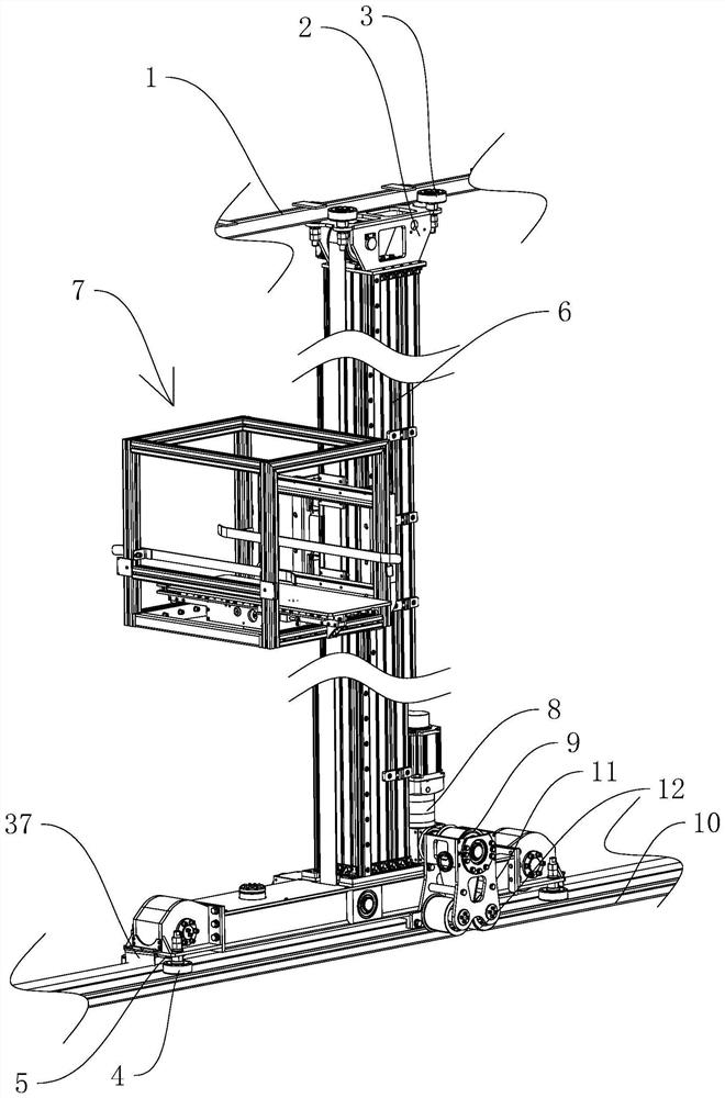
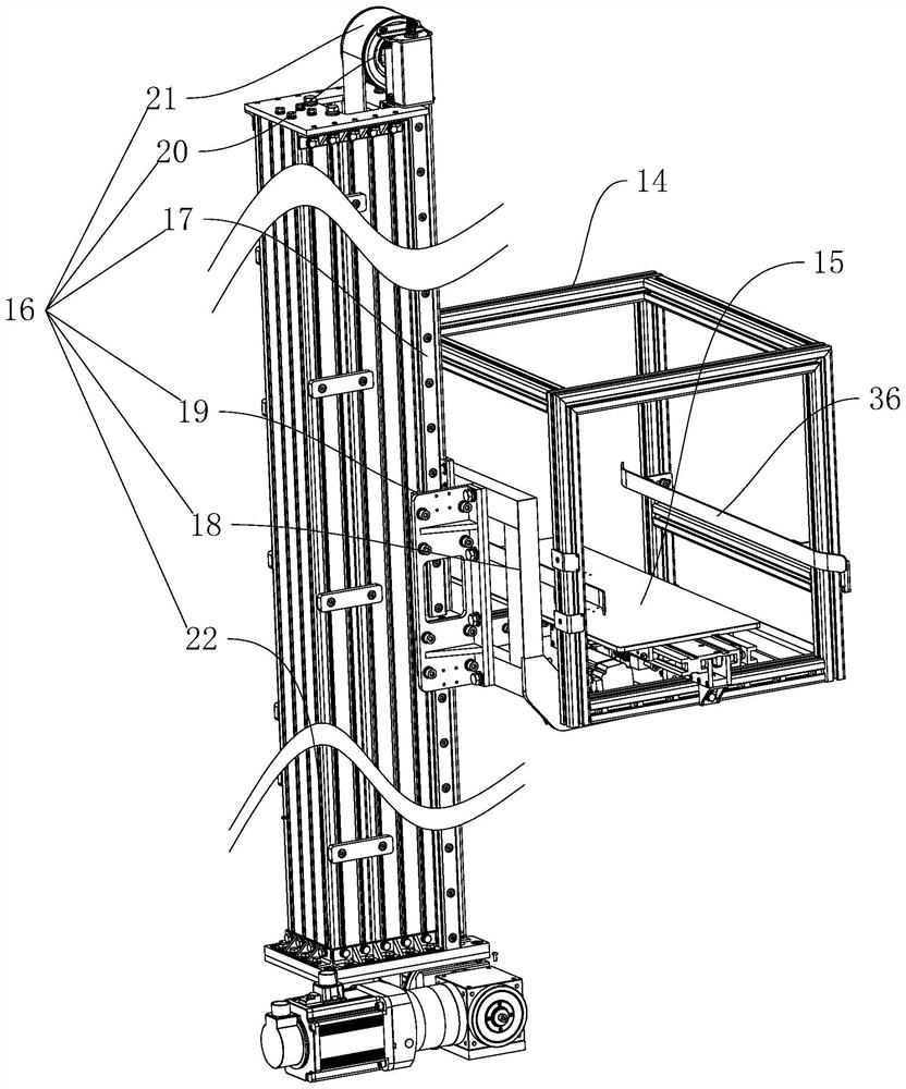
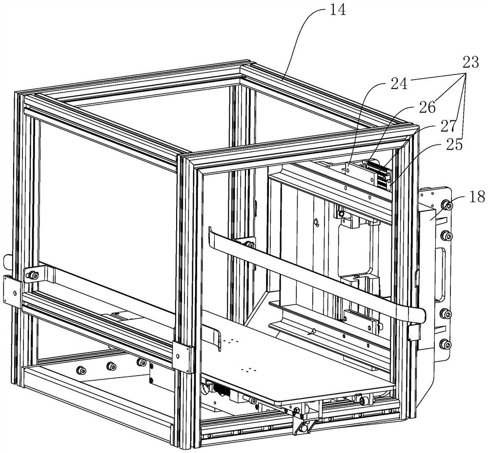
[0024] like figure 1 , figure 2 , image 3 , Figure 4 As shown, a stacker includes two slide rails 1 arranged up and down, a stacker body is arranged between the two slide rails 1, and the stacker body includes two brackets slidably connected to the slide rails 1 2. First rollers 3 are rotatably connected to the two side walls of both ends of the upper bracket 2, the first roller 3 is abutted on the side walls of the slide rail 1, and both sides of both ends of the lower bracket 2 are rotatably connected. There is a second roller 4, the second roller 4 abuts on the side wall of the slide rail 1, and a third roller 5 is rotatably connected to the lower surfaces of both ends of the lower bracket 2, and the third roller 5 rolls o...


PUM


Abstract

The invention provides a stacking machine convenient to use, and belongs to the technical field of stacking equipment, the stacking machine comprises two sliding rails arranged up and down, a stacking machine body arranged between the two sliding rails, a first motor fixedly connected to the stacking machine body, a first synchronous wheel fixedly connected to an output shaft of the first motor, and a second synchronous wheel fixedly connected to an output shaft of the second motor. A first synchronous belt is fixedly connected to the ground, teeth of the first synchronous belt face the ground, the first synchronous belt is meshed with the first synchronous wheel, the first synchronous wheel is located below the first synchronous belt, and an abutting mechanism used for enabling the first synchronous belt to be meshed with the first synchronous wheel all the time is arranged on the stacking machine body. The support has the advantage that the sliding accuracy of the support on the sliding rail is improved.

Description

technical field [0001] The invention belongs to the technical field of stacking equipment, in particular to a stacker. Background technique [0002] The function of the palletizer is to stack the cartons that have been loaded into the container on the pallets and pallets (wood, plastic) in a certain arrangement, and perform automatic stacking. [0003] During the use of the existing stacker, the stacker directly slides on the slide rail, and the motor directly drives the roller, and the roller slides on the slide rail. During the use of this driving method, the roller is easily connected to the slide rail. There is slippage and slippage, which leads to the insufficient conveying distance of the stacker, so that it cannot be delivered to the predetermined location. SUMMARY OF THE INVENTION [0004] The purpose of the present invention is to solve the above problems in the prior art, and propose a stacker, which has the characteristics of improving the sliding accuracy of t...

Claims


Application Information

Patent Timeline
Patent Type & Authority Applications(China)
IPC IPC(8): B66F9/07B66F9/24B66F9/12B66F9/075
CPCB66F9/072B66F9/24B66F9/12B66F9/07504
Inventor 王宇俞酃
Owner 平湖市开浦机电集成有限公司
Learn More