Method for monitoring frictional wear state by using frictional electric signal

A friction and wear, electrical signal technology, applied in the field of friction, can solve the problems of damage, poor sensitivity and wear of the two friction surfaces of the friction pair, and achieve the effect of easy installation, sensitive response, and dynamic monitoring.

Pending Publication Date: 2022-06-28
LANZHOU INST OF CHEM PHYSICS CHINESE ACAD OF SCI +1
View PDF0 Cites 0 Cited by
  • Summary
  • Abstract
  • Description
  • Claims
  • Application Information

AI Technical Summary

Problems solved by technology

The disadvantages of this method are: 1. To test two surfaces that are attached to each other, there are certain difficulties in the layout of the test instruments, and it is impossible to accurately measure the dynamic temperature of the friction surface; 2. For some friction pairs with small contact surfaces, the area The temperature difference of the friction pair is very small, which increases the difficulty of measurement to a certain extent; 3. When a large temperature rise is detected, it means that the two friction surfaces of the friction pair have been worn out, and an early warning cannot be issued before the wear
The disadvantage of this method is that the two friction surfaces of the diagnosed friction pair have been seriously damaged, and the diagnosis of early friction pair faults is not sensitive enough.
The disadvantage of this method is that it cannot predict sudden failures in time, and it is highly dependent on the experience of personnel.
The disadvantage of this method is that the contact resistance of the two surfaces will change greatly after the oil film is completely broken, but at this time the lubricant lubrication has completely failed, and the surfaces of the two friction pairs have been rubbing for a period of time in a poor lubrication state , may have been severely worn
[0013] To sum up, the current friction and wear monitoring methods all have the problem of poor sensitivity, and cannot give an early warning when the lubrication starts to deteriorate

Method used


Image

  • Method for monitoring frictional wear state by using frictional electric signal
  • Method for monitoring frictional wear state by using frictional electric signal
  • Method for monitoring frictional wear state by using frictional electric signal

Examples


Embodiment 1

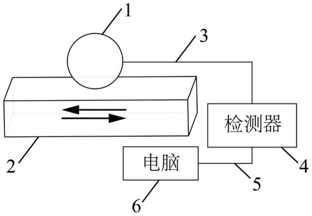
[0060] Real-time monitoring of friction and wear status of rolling bearings. Rolling bearings are composed of rolling elements, outer rings and inner rings. The materials of rolling elements, outer rings and inner rings are high carbon bearing steel (GCr15). The rolling bearings are lubricated with liquid lubricants. friction movement. The monitoring device is connected as Figures 7 to 8 As shown, one end of the wire 3 is connected to the outer ring, and the other end is connected to a current amplifier, and the current amplifier transmits the triboelectric signal to the computer 6 through the data cable 5 .

[0061] The detected triboelectric signals such as Figure 9 shown. Figure 9 The dotted box 1 is the triboelectric signal under normal friction and lubrication conditions of the friction pair, which is 50nA, and the triboelectric signal of the friction pair in the dotted box 2 is slightly worn. It can be seen that discharge will occur at this time, and the current dur...


PUM


Abstract

The invention relates to the technical field of friction, and provides a method for monitoring a frictional wear state by using a frictional electric signal. Friction electric signals generated in the friction movement process of the friction pair are monitored, and the friction wear state of the two friction surfaces is judged according to the monitored friction electric signals. According to the method, the lubrication state in the friction pair can be monitored, abrasion caused by lubrication failure is avoided, the friction pair can be dynamically monitored in real time, response is sensitive, monitoring can be conducted on the premise that the friction pair is not opened or damaged, and a measuring device is easy and convenient to install; furthermore, the method provided by the invention is suitable for various friction pairs, the contact modes comprise point contact, line contact and surface contact, and the motion modes comprise linear motion, linear reciprocating motion and rotary motion.

Description

technical field [0001] The invention relates to the technical field of friction, in particular to a method for monitoring friction and wear state by using triboelectric signals. Background technique [0002] Among the various failure modes of equipment, wear failure and its adverse effects account for the highest proportion. Lubrication is the use of lubricating medium to reduce the friction between two friction surfaces to reduce wear. Due to the gap between people's understanding of the complex physical and chemical processes in the tribological system and the objective reality, there are many uncertainties in the actual operation process. Due to the influence of sexual factors, no matter how perfect the design is, it is difficult to ensure that the equipment is always in a good lubrication state. Therefore, it is very necessary to dynamically monitor the lubrication and wear conditions during equipment operation. [0003] With the increasing development of equipment to ...

Claims


Application Information

Patent Timeline
IPC IPC(8): G01R31/12F16C41/00
CPCG01R31/1263F16C41/00F16C2233/00
Inventor 王道爱冯雁歌刘祥周峰刘维民
Owner LANZHOU INST OF CHEM PHYSICS CHINESE ACAD OF SCI
Why Eureka
Try Eureka