
Measuring mechanism for light lens processing

A lens processing and measurement mechanism technology, applied in the direction of mechanical thickness measurement, conveyor objects, transportation and packaging, etc., can solve the problems that the thickness of the lens cannot be fully grasped, it is difficult to improve the quality control, and the lens inspection cannot be achieved, so as to ensure the assembly line, Improve efficiency and ensure continuous effect

Active Publication Date: 2022-06-28
菏泽鲁信光学科技有限公司
View PDF4 Cites 2 Cited by
  • Summary
  • Abstract
  • Description
  • Claims
  • Application Information

AI Technical Summary

Problems solved by technology

[0002] The surface of the sun visor has a certain curvature. In the processing of light lenses such as sun visors, the resin raw material is melted and injected into the mould, and then stamped. After polishing and cleaning, before the final packaging, the staff needs to check the thickness of the lens. Strict control, it is a common way for workers to measure the thickness with a caliper meter, and get the thickness of the lens through the reading of the pointer on the dial, but this method is very inconvenient and inefficient in actual operation, and can only be carried out on the lens one by one Measure and check one by one; in order to improve efficiency, in the existing measurement, sampling surveys are carried out in batches and spot checks to improve efficiency, but this method cannot be used to check every lens, so that the thickness of the obtained lenses cannot be determined. Comprehensive grasp, difficult to improve quality control

Method used


Image

  • Measuring mechanism for light lens processing
  • Measuring mechanism for light lens processing
  • Measuring mechanism for light lens processing

Examples


Embodiment Construction

[0032] The following description serves to disclose the invention to enable those skilled in the art to practice the invention. The preferred embodiments described below are given by way of example only, and other obvious modifications will occur to those skilled in the art.

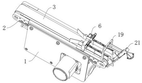
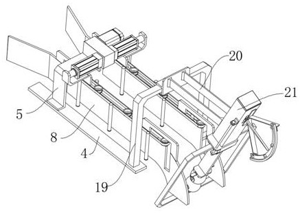
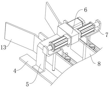
[0033] like Figure 1-Figure 13 The shown measuring mechanism for optical lens processing includes a base 1, a frame 2 fixedly mounted on the upper end of the base 1, a conveyor belt 3 movably arranged on the outer surface of the frame 2, and the upper surface of the conveyor belt 3 passes through a bidirectional telescopic mechanism. Two symmetrical guide plates 8 are provided, the front end of the guide plate 8 extends out of an arc-shaped plate 18 adapted to the front end of the conveyor belt 3, and two sides of each guide plate 8 are synchronously driven by a synchronous wheel mechanism. And keep only the lower end of the toggle lever 16 on the side of the guide plate 8 in contact with the surface o...


PUM


Abstract

The invention relates to the technical field of lens measurement, in particular to a measuring mechanism for light lens processing, which comprises a base, a frame fixedly mounted at the upper end of the base and a conveying belt movably arranged on the outer surface of the frame, and two symmetrical guide plates are arranged on the upper surface of the conveying belt through a bidirectional telescopic mechanism. The front end of each guide plate extends to form an arc-shaped plate adaptive to the front end of the conveying belt, a plurality of poke rods are arranged on the two sides of each guide plate in a synchronous transmission mode through a synchronous wheel mechanism, and only the lower ends of the poke rods located on one side of each guide plate are kept to make contact with the surface of the conveying belt. The lens thickness measuring device can be applied to a conveying line, it is guaranteed that continuous conveying of lenses is not affected, the thickness of the lenses is continuously measured, the lenses do not need to be manually arranged in the measuring process, the measuring efficiency is greatly improved, and the continuity of the whole conveying line is guaranteed.

Description

technical field [0001] The present invention relates to the technical field of lens measurement, in particular to a measurement mechanism used for optical lens processing. Background technique [0002] The surface of the sunshade mirror has a certain curvature. In the processing of light lenses such as sunshade mirrors, the resin raw material is melted and injected into the mold and then stamped. After polishing and cleaning, before the final packaging, the thickness of the lens needs to be checked by the staff. Strict control. It is a common way for workers to measure the thickness through a caliper meter. The thickness of the lens is obtained by reading the pointer on the dial. However, this method is very inconvenient and inefficient in actual operation. Measurement and investigation one by one; in order to improve efficiency, sampling surveys are conducted in batches in the existing measurement to improve efficiency, but this method cannot check each lens, so that the th...

Claims


Application Information

Patent Timeline
Patent Type & Authority Applications(China)
IPC IPC(8): G01B5/06B65G47/24
CPCG01B5/06B65G47/24
Inventor 毕景云陈冠华王未陈海军
Owner 菏泽鲁信光学科技有限公司
Learn More