


Quick Research
Generate reliable direction feasibility study reports for your R&D in just a few steps.

Technical Q&A
Discover and master advanced knowledge NOW. Basics, ideas, possibilities, all at once.

Find Solutions
As an expert in R&D theories, this can generate solutions to your technical problems instantly.

Evaluate Feasibility
Analyze your overall solution with one click, know your potential R&D risks in advance.

Monitor Landscape
Get weekly tech updates, stay abreast of the latest tech innovations and key insights.
Positioning mold for engine ceramic core material development and positioning method thereof
A ceramic core and positioning mold technology, applied in the direction of core, mold, mold composition, etc., can solve the problems of complex structure, unfavorable device use, precision impact, etc., to achieve accurate position, prevent movement, and reduce waste products.
- Summary
- Abstract
- Description
- Claims
- Application Information
AI Technical Summary
Problems solved by technology
Method used
Image

Examples
Embodiment 1
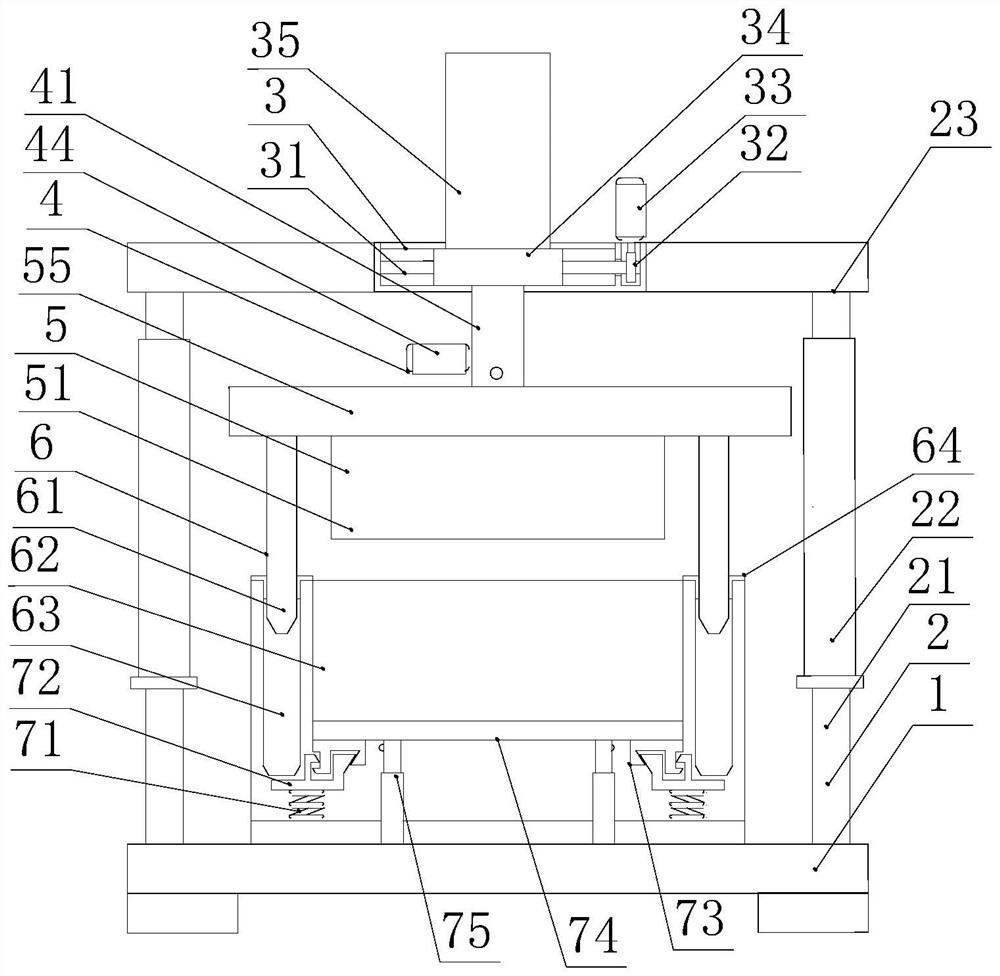
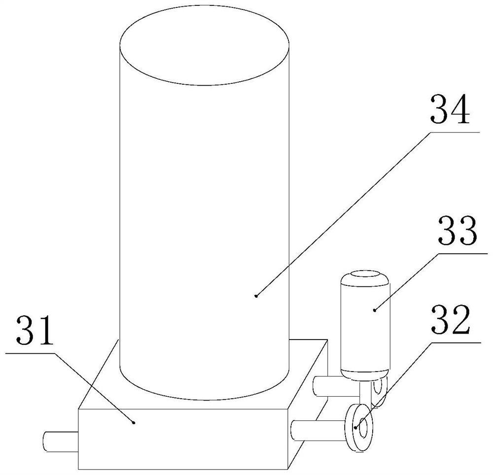
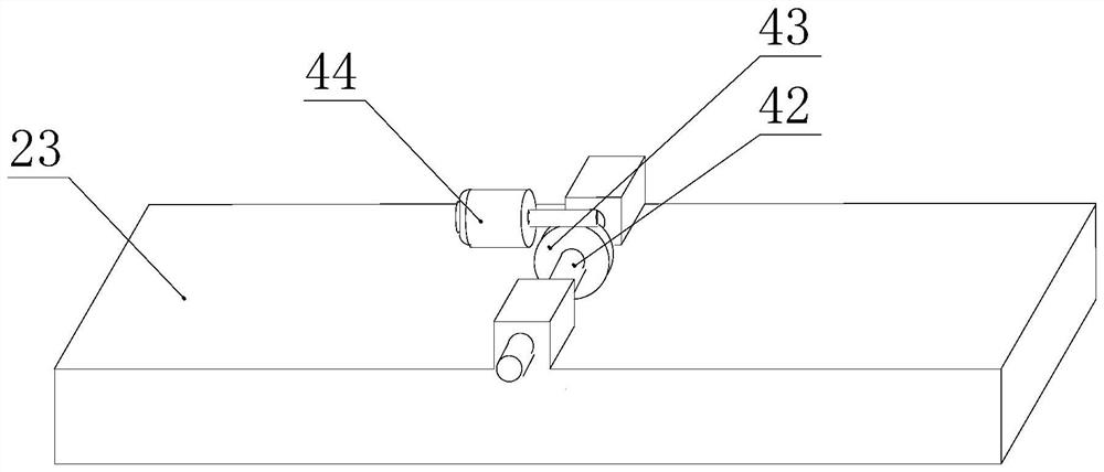
[0029] see Figure 1-3 , this embodiment provides a positioning mold for the development of an engine ceramic core material and a positioning method thereof, including a base 1, and an adjustment mechanism 2 is provided on the top of the base 1, and the height of the device is easily adjusted through the adjustment mechanism 2. One end of the top of the adjustment mechanism 2 There is a left and right moving mechanism 3. The bottom of the left and right moving mechanism 3 is provided with a front and rear moving mechanism 4. By using two moving mechanisms, it is convenient to adjust the position of the punch 51. The bottom of the front and rear moving mechanism 4 is provided with a heating mechanism 5, which is convenient for heating the equipment. , the top of the base 1 is provided with a positioning mechanism 6 between the adjustment mechanisms 2, by using the position of the punch 51 and the female mold 62 to locate, the positioning mechanism 6 is provided with an ejection ...
Embodiment 2
[0035] see figure 1 , made further improvements on the basis of Example 1:
[0036]In order to facilitate the adjustment of the upper and lower heights of the device and facilitate the feeding and discharging of materials, the adjustment mechanism 2 includes two fixing rods 21. The top ends of the base 1 are fixedly connected with the fixing rods 21, and one end of the fixing rod 21 near the top is fixedly connected with a hydraulic lifting rod 22. The top end of the hydraulic lifting rod 22 is fixedly connected to the bottom of the top plate 23, and the four corners of the bottom of the base 1 are adhered with shock-absorbing pads. The hydraulic lifting rod 22 drives the top plate 23 to move up and down, which is convenient for changing the height of the device. shock absorption.
Embodiment 3
[0038] see figure 1 and Figure 4 , made further improvements on the basis of Example 1:
[0039] In order to facilitate the heating of the device, the heating mechanism 5 includes a punch 51, the top of the punch 51 is fixedly connected to the movable plate 55, a heater 52 is fixedly connected inside the punch 51, and both ends of the heater 52 are fixedly connected with heating terminals 53 , the heating terminal 53 is wrapped with a heating pipe 54, and the heating pipe 54 is heated by the heater 52, which is convenient for the use of the device and prevents the cooling speed from being too fast and affecting the quality of the product.
PUM
 Abstract
Description
Claims
Application Information
 - R&D Engineer
- R&D Manager
- IP Professional
- Industry Leading Data Capabilities
- Powerful AI technology
- Patent DNA Extraction
Browse by: Latest US Patents, China's latest patents, Technical Efficacy Thesaurus, Application Domain, Technology Topic, Popular Technical Reports.
© 2024 PatSnap. All rights reserved.Legal|Privacy policy|Modern Slavery Act Transparency Statement|Sitemap|About US| Contact US: help@patsnap.com