
Pipeline filter pressure testing machine

A pipeline filter and pressure testing technology, which is applied in the testing of machine/structural components, testing of mechanical components, and by measuring the rate of increase and deceleration of fluids, can solve the problem of reducing detection efficiency, affecting detection accuracy, and uneven pressure distribution and other issues to achieve the effect of improving accuracy, improving the effect of detection, and strengthening stability

Pending Publication Date: 2022-06-24
台州重友焊接科技有限公司
View PDF0 Cites 0 Cited by
  • Summary
  • Abstract
  • Description
  • Claims
  • Application Information

AI Technical Summary

Problems solved by technology

[0004] The inventor believes that: due to the fine and dense filter layer and powder filter layer in the pipeline filter, there will be uneven pressure distribution after the gas enters the pipeline filter, and there will be hysteresis, which will reduce the efficiency of detection, thereby affecting the accuracy of detection

Method used


Image

  • Pipeline filter pressure testing machine
  • Pipeline filter pressure testing machine
  • Pipeline filter pressure testing machine

Examples


Embodiment 1

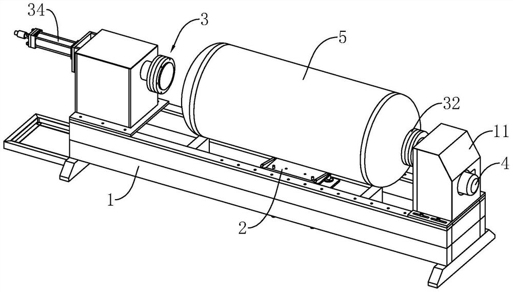
[0042] refer to figure 1 , the pressure testing machine includes a base 1, a support component 2 installed on the base 1, a support component 3 installed above the base 1, and a rotating component 4 installed on the base 1 to drive the support component 3 to rotate. There is a pipeline filter 5, the support component 2 is used to send the pipeline filter 5 between the supporting components 3, and the rotating component 4 can also charge air into the pipeline filter 5 for pressure testing.

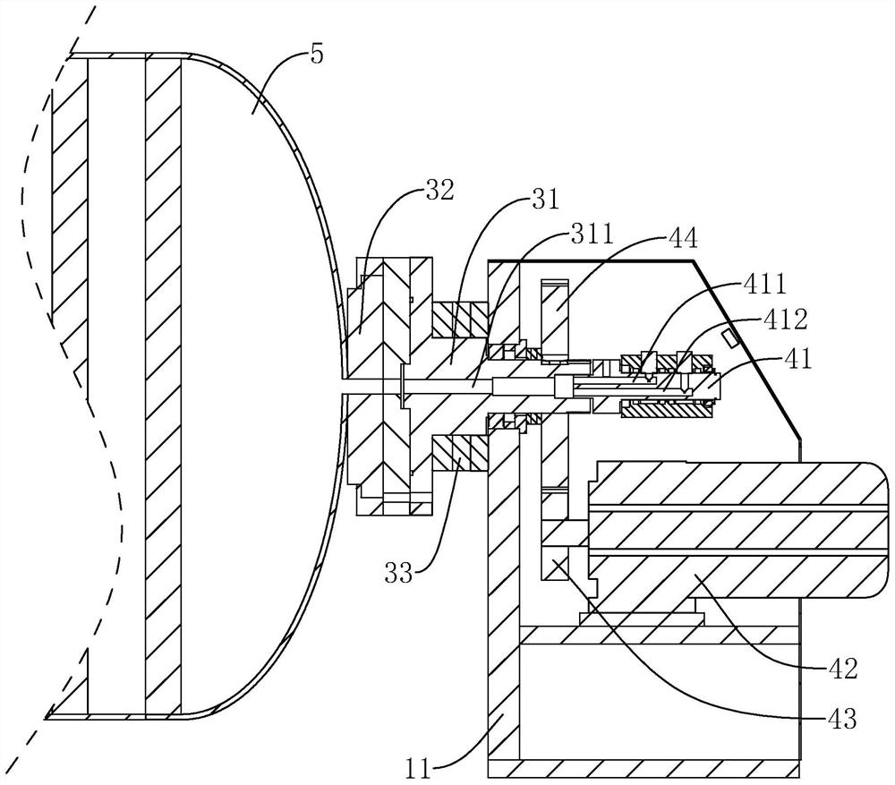
[0043] refer to figure 1 and figure 2 , the two ends of the base 1 are fixedly connected with the positioning box 11, and the holding assembly 3 includes a rotating shaft 31 that rotates on the positioning box 11, an abutting member installed on the rotating shaft 31, and a fixed connection on the positioning box 11 to drive the rotating shaft 31 to slide. The cylinder 34 is clamped, and the abutting member includes an elastic pad 32 sleeved on the end of the rotating shaft 31 and abutti...

Embodiment 2

[0054] The difference between this embodiment and Embodiment 1 is that the driving source for driving the supporting plate 27 to ascend and descend is different. .

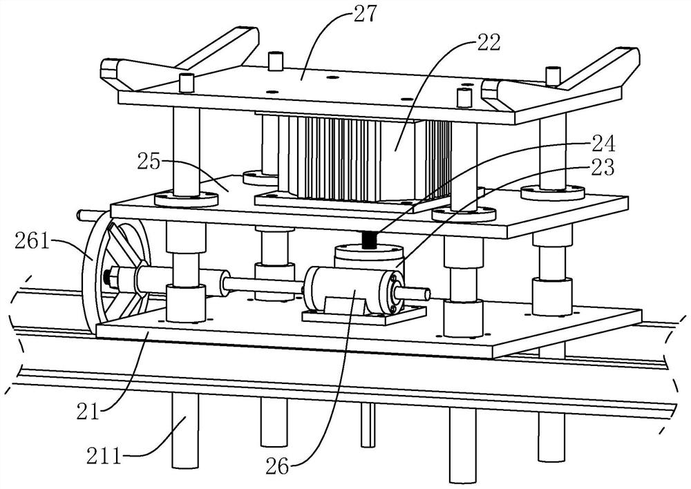
[0055] refer to Figure 4 and Figure 5 , the sliding plate 21 is slidably connected with the sliding seat 6 located on both sides of the threaded rod 24, the sliding seat 6 is located between the guide rods 211 in the length direction of the base 1 and slides, and the sliding seat 6 slides along the sliding direction perpendicular to the sliding plate 21, Both ends of the worm 26 pass through and are rotatably connected to the sliding seat 6 to drive the worm 26 to slide toward or away from the turbine 23 .

[0056] refer to Figure 5 One end of the sliding seat 6 is also fixedly connected with a second motor 62 that drives the worm 26 to rotate. The bottom wall of the support plate 27 is fixedly connected with a lifting rod 63, the lifting rod 63 slides through the bottom plate 25 and the slide plate 21, and...


PUM


Abstract

The invention relates to a pipeline filter pressure testing machine, and relates to the technical field of gas filtration, and the pipeline filter pressure testing machine comprises a pedestal, a pipeline filter rotatably arranged on the pedestal, abutting members abutting against two ends of the pipeline filter are arranged on the pedestal, and rotating shafts driving the abutting members to rotate are rotatably arranged at two ends of the pedestal. The rotating shaft slides on the base in the direction of the rotating axis of the rotating shaft, a clamping air cylinder for driving the rotating shaft to slide and driving the abutting piece to clamp the pipeline filter is arranged on the base, a rotating assembly for driving the rotating shaft away from the air cylinder to rotate is further arranged on the base, and the rotating assembly is further used for filling gas into the pipeline filter. According to the pipeline filter, the rotating shaft is arranged, so that the pipeline filter rotates, internal air can be quickly and uniformly distributed, powder filtered matter shakes, powder is loose, gaps are generated among the powder, air can pass through the pipeline filter conveniently, the detection effect is improved, and the pipeline filter has the advantage of improving the detection accuracy.

Description

technical field [0001] The present application relates to the technical field of gas filtration, and in particular, to a pressure testing machine for pipeline filters. Background technique [0002] At present, with the gradual improvement of people's quality of life, special attention is paid to the air quality of the environment. Therefore, various air filters are randomly sold in the market. In the environment with large space such as factories, pipeline filters are used for air filtration. , and the performance of the pipeline filter needs to be pressure tested at the factory. [0003] Generally, there are multiple layers of fine filter layers and powder filter layers in the pipeline filter to filter the air. During the test, one end of the pipeline filter is blocked, and the other end is fed with compressed air, and the leak is detected by the pressure gauge. [0004] The inventor believes that due to the fine filter layer and powder filter layer in the pipeline filter,...

Claims


Application Information

Patent Timeline
Patent Type & Authority Applications(China)
IPC IPC(8): G01M13/00G01M3/26
CPCG01M13/00G01M3/26
Inventor 朱多友
Owner 台州重友焊接科技有限公司
Learn More