
Floor type electronic accelerator pedal

An electronic accelerator pedal, floor type technology, applied in the layout of the power unit control mechanism, vehicle components, transportation and packaging, etc., can solve the problem of inconsistent performance of the finished accelerator pedal, unfavorable spring seat fully assembled in place, spring seat installation and maintenance. Trouble and other problems, to achieve the effect of improving structural reliability and performance consistency, excellent machinability and detectability, and simple installation structure

Pending Publication Date: 2022-06-24
NANJING AOLIAN AE&EA
View PDF1 Cites 0 Cited by
  • Summary
  • Abstract
  • Description
  • Claims
  • Application Information

AI Technical Summary

Problems solved by technology

[0003] 1. After long-term use, the rocker arm produces a large force empty stroke, resulting in a slow response to the force value of the accelerator pedal, and a rapid drop in hysteresis force, and the arc-shaped friction part of the rocker arm will produce irregular wear, affecting The linear output of the electronic accelerator pedal force value makes the pedal stability worse
[0004] 2. The existing assembly method makes the friction arc surface of the spring seat blocked by the rocker arm, which is not conducive to identifying whether the spring seat is fully assembled in place. The installation and maintenance of the spring seat are more troublesome, and the semi-circular structure of the rocker arm makes the design of related fixtures Poor performance, reduced quality controllability when manufacturing parts, resulting in inconsistent performance of the finished gas pedal

Method used


Image

  • Floor type electronic accelerator pedal
  • Floor type electronic accelerator pedal
  • Floor type electronic accelerator pedal

Examples


no. 1 Embodiment approach

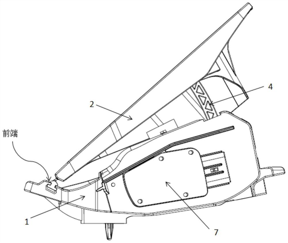
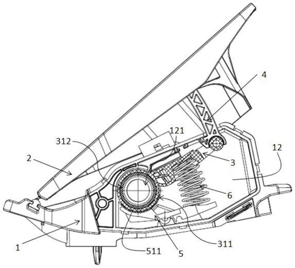
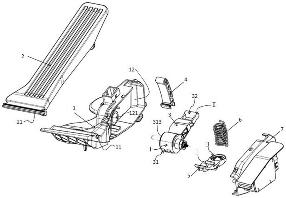
[0032] see Figure 1 to Figure 9 , This embodiment provides a floor-type electronic accelerator pedal with hysteresis effect, including a base 1 , a pedal surface 2 , a rocker arm 3 , a rocker arm bracket 4 , a spring seat 5 , a return spring 6 and an electronic box 7 . The rocker arm 3, the rocker arm bracket 4, the spring seat 5 and the return spring 6 constitute a hysteresis mechanism. The return spring 6 is a double helical cylindrical spring.

[0033] The right side of the base 1 is provided with an open inner cavity 12, the open inner cavity 12 is provided with a cylindrical positioning shaft 121, and the outer circumference of the root of the cylindrical positioning shaft 121 is coaxially provided with an annular boss (not shown in the figure). ), an annular slot is formed between the annular boss and the cylindrical positioning shaft (121), and the annular slot is used to rotatably connect the rocker arm. In this embodiment, the cylindrical positioning shaft 121 and ...


PUM


Abstract

The invention discloses a floor type electronic accelerator pedal which comprises a base, a pedal face, a rocker arm support, a rocker arm, a reset spring and a spring seat. A cylindrical positioning shaft is arranged in an inner cavity of the base, a cylindrical friction part is arranged at one end of the rocker arm, the rocker arm is rotatably assembled in the inner cavity of the base through the cylindrical positioning shaft, and the inner circumferential wall of the cylindrical friction part is in friction and rotation connection with the outer circumferential wall of the cylindrical positioning shaft; the spring seat is rotatably assembled in the inner cavity of the base, and the arc-shaped friction part of the spring seat is in friction and rotation connection with the outer circumferential wall of the cylindrical friction part of the rocker arm. According to the invention, the stress idle stroke is small, the force value response of the accelerator pedal is fast, the linear output is stable, and the technical effects that the pedal can be always kept at the original position, the angle of the accelerator is not changed and the driving process is more stable and comfortable even on a very bumpy road surface can be realized.

Description

technical field [0001] The invention relates to the technical field of automobile manufacturing, in particular to a floor-type electronic accelerator pedal. Background technique [0002] The applicant of the present application has developed a floor-type electronic accelerator pedal with hysteresis effect with the patent number of CN109334449A. In this patent, a hysteresis mechanism is arranged between the foot pedal and the base to achieve the effect of the pedal maintaining hysteresis during driving; However, the assembling method of the existing hysteresis mechanism is as follows: the spring seat is sleeved on the inner side of the rocker arm and then placed in the inner cavity of the base, the rocker arm is rotatably supported between the arc surface of the base and the spring seat, and the outer arc friction surface of the rocker arm is connected to the base. The inner arc-shaped surface is frictionally and rotatably connected, and the inner arc-shaped friction surface ...

Claims


Application Information

Patent Timeline
Patent Type & Authority Applications(China)
IPC IPC(8): B60K26/02
CPCB60K26/02
Inventor 张杰曾盼盼程健卢新田
Owner NANJING AOLIAN AE&EA
Learn More