Electrical tool storage device

A tool storage and electrical technology, applied in the direction of tool storage devices, manufacturing tools, etc., can solve the problems of different types of electrical tools positioning, inability to cool down electrical tools, damage to electrical tools, etc., to achieve convenient operation and good cooling treatment , anti-aging effect

Inactive Publication Date: 2022-06-24
YANTAI ENG & TECH COLLEGE YANTAI TECHNICIAN INST
View PDF0 Cites 1 Cited by
  • Summary
  • Abstract
  • Description
  • Claims
  • Application Information

AI Technical Summary

Problems solved by technology

[0003] Traditional storage devices are generally simple in structure and function, and can only be used to store electrical tools. In actual use, due to the wide variety of electrical tools and different shapes and structures, traditional storage devices cannot be used for different types of tools. Fast positioning of the electrical tools, and then moving the storage device when the positioning is unstable, may damage the electrical tools due to bumps, resulting in losses. At the same time, the traditional storage device cannot cool the electrical tools well.

Method used


Image

  • Electrical tool storage device
  • Electrical tool storage device
  • Electrical tool storage device

Examples


Embodiment 1

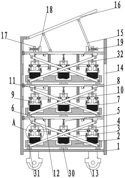
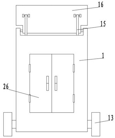
[0022] see Figure 1-4 , an electrical tool storage device, including a storage box 1, and also includes: a cover plate 16 arranged on one side of the storage box 1, one end of the cover plate 16 is rotatably connected to the top wall of the storage box 1, and the storage box 1 is slidably arranged inside The movable plate 6; the storage mechanism 30 arranged on one side of the movable plate 6 includes the carrier tray 2 arranged on one side of the movable plate 6, wherein the object tray 2 arranged above the movable plate 6 is rotatably connected with the movable plate 6, and is located in the movable plate 6. The carrier tray 2 at the bottom of the storage box 1 is rotatably connected to the bottom of the storage box 1. A transmission assembly 31 is provided on one side of the carrier tray 2, and a mounting plate 4 is arranged between the carrier tray 2 and the movable plate 6. The mounting plate 4. Limiting posts 10 are arranged through sliding at both ends, one end of the ...

Embodiment 2

[0025] see Figure 1-4 , the other contents of this embodiment are the same as those of Embodiment 1, the difference is that: the transmission assembly 31 includes movable blocks 8 slidably arranged on both sides of the bottom of the movable plate 6, and one end of the movable block 8 is hinged to the transmission rod 3, and the movable block 8 is hinged to the transmission rod 3. One end of the transmission rod 3 between the plates 6 away from the movable block 8 is hingedly connected to the movable plate 6 , and one end of the transmission rod 3 at the bottom of the storage box 1 is hingedly connected to the bottom wall of the storage box 1 .

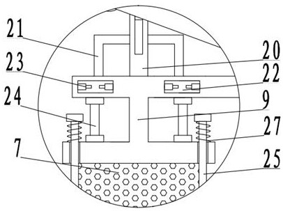
[0026] The pumping assembly 32 includes an installation cylinder 20, the installation cylinder 20 is fixedly arranged on the installation plate 4, the inner upper end of the installation cylinder 20 is slidably connected to the piston rod 5, and the top of the piston rod 5 is fixedly connected to the movable plate 6. The installation c...


PUM


Abstract

The invention discloses an electrical tool storage device, and relates to the technical field of tool storage, the electrical tool storage device comprises a storage box and further comprises a cover plate arranged on one side of the storage box, one end of the cover plate is rotatably connected with the top wall of the storage box, and a movable plate is slidably arranged in the storage box; the storage mechanism is arranged on one side of the movable plate and comprises a carrying disc arranged on one side of the movable plate, the carrying disc located on the lowermost portion of the storage box is rotationally connected with the bottom of the storage box, a transmission assembly is arranged on one side of the carrying disc, one side of the bottom of a bearing rod is fixedly connected with a telescopic air bag, and the two sides of the telescopic air bag are fixedly connected with limiting rods. A first storage groove and a second storage groove are formed in the side, corresponding to the object carrying disc, of the telescopic air bag, an air pumping assembly is arranged between the mounting plate and the movable plate, during actual storage, under the action of the transmission assembly, the movable plate and the object carrying disc get close to each other, and the air pumping assembly sends air into the telescopic air bag; the telescopic air bag expands and presses the electrical tools on the carrying disc, and fixed storage is achieved.

Description

technical field [0001] The invention relates to the technical field of tool storage, in particular to an electrical tool storage device. Background technique [0002] Electrical equipment is a general term for generators, transformers, power lines, circuit breakers and other equipment in the power system. The important role that electricity plays in our life and production cannot be ignored. Important energy in production and life. The most critical factor for the normal operation and transmission of electricity in a power plant is the electrical equipment. When the electrical equipment is overhauled and maintained, special electrical tools will be required for the work. In order to facilitate the transportation and taking of the tools, generally Tools will be placed inside the storage box. [0003] The traditional storage device is generally simple in structure and function, and can only play the role of storing electrical tools. In actual use, due to the wide variety of ...

Claims


Application Information

Patent Timeline
Patent Type & Authority Applications(China)
IPC IPC(8): B25H3/00
CPCB25H3/00
Inventor 解增昆肖苏慧
Owner YANTAI ENG & TECH COLLEGE YANTAI TECHNICIAN INST
Why Eureka
Try Eureka