
Brake band for disc of ventilated disc brake

A technology of disc brakes and brake bands, applied in the direction of brake components, brake discs, brake types, etc., can solve problems such as incomplete solutions, avoid blocking or excessively restricting ventilation channels, increase quality, and improve discs The effect of cooling efficiency

Pending Publication Date: 2022-06-17
FRENI BREMBO SPA
View PDF46 Cites 0 Cited by
  • Summary
  • Abstract
  • Description
  • Claims
  • Application Information

AI Technical Summary

Problems solved by technology

[0032] This known solution, although satisfactory from many points of view, does not completely solve the problem, and particularly highlights the search for a solution that can easily create a surface shape that delimits the gap between the brake bands needs

Method used


Image

  • Brake band for disc of ventilated disc brake
  • Brake band for disc of ventilated disc brake
  • Brake band for disc of ventilated disc brake

Examples


Embodiment Construction

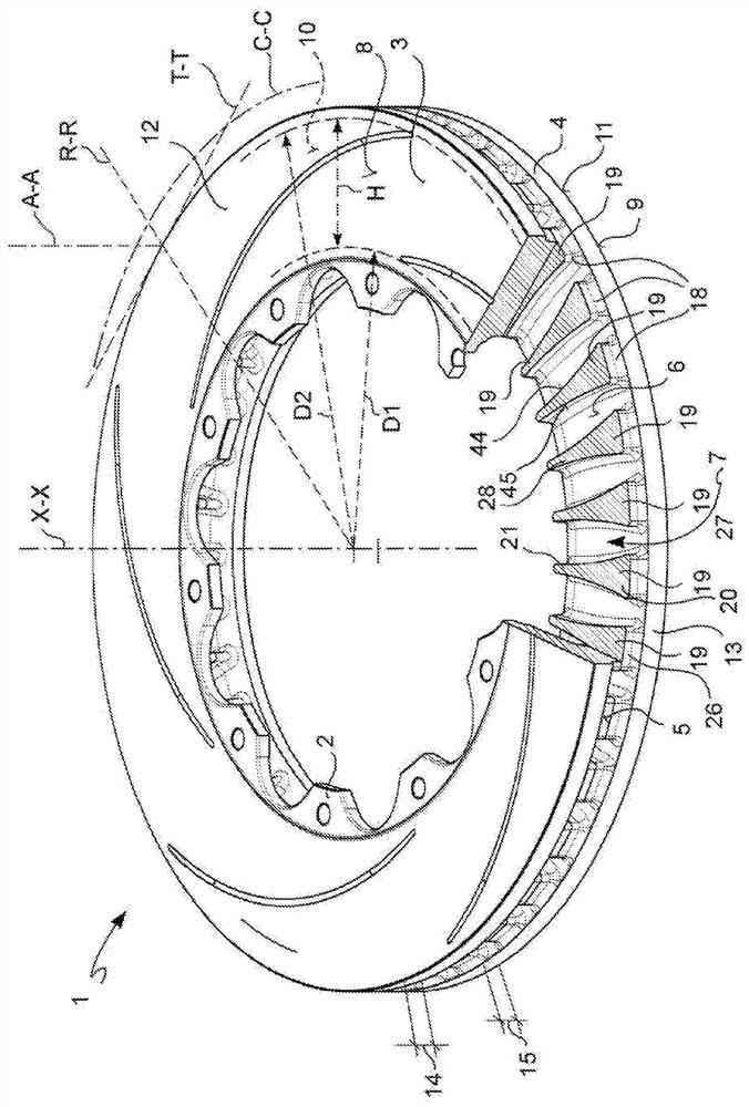
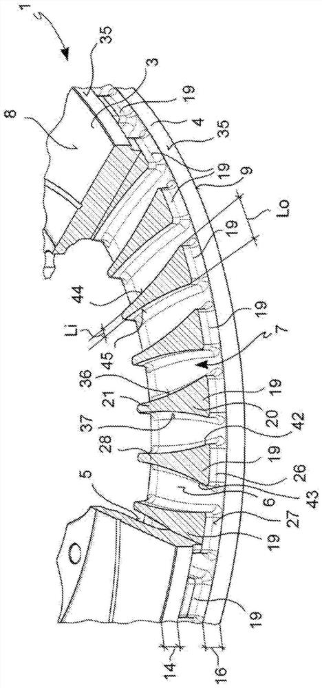
[0063] According to a general embodiment, a brake band 1 for a disc of a ventilated disc brake 2 is provided.

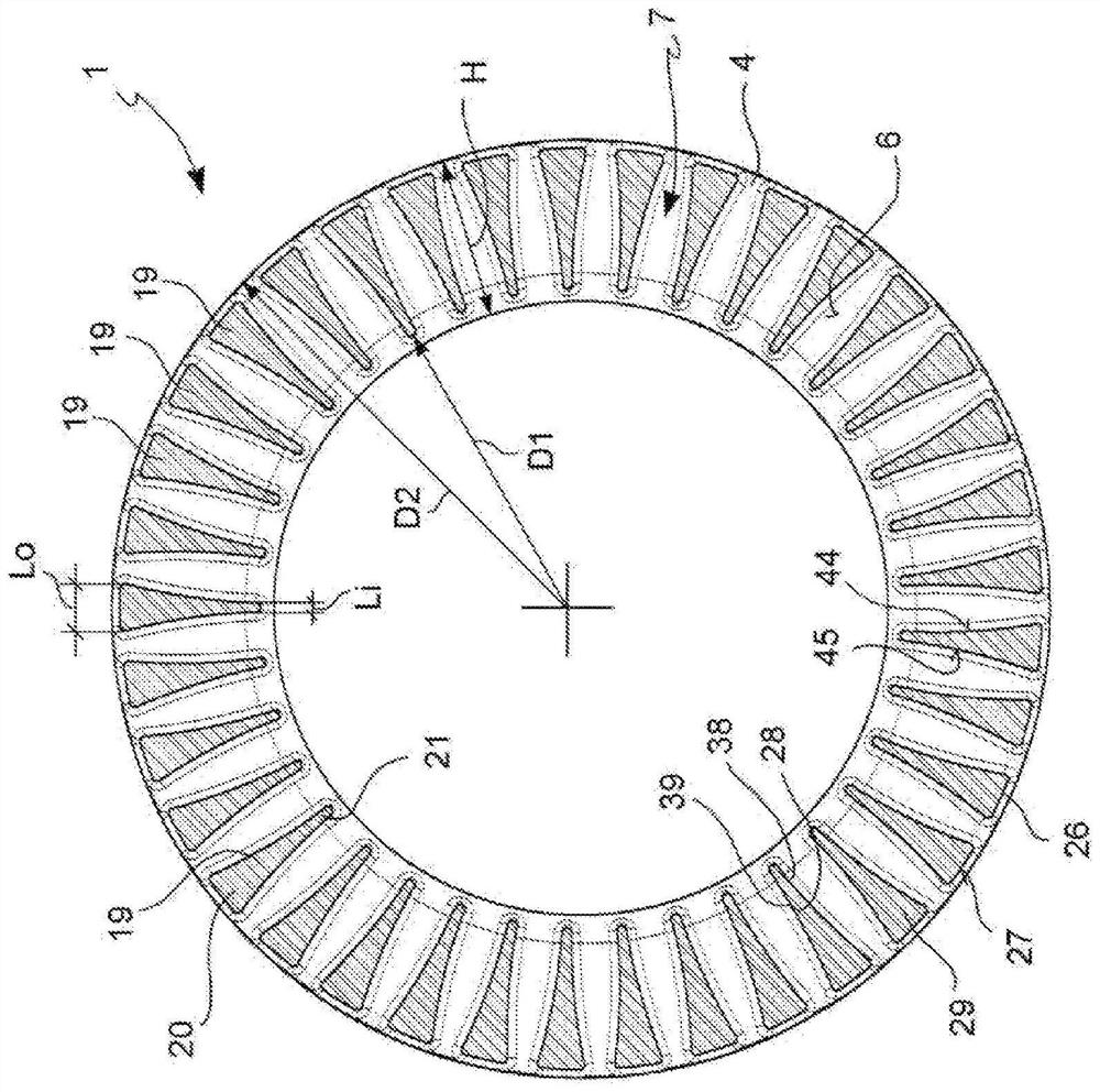
[0064] The brake band 1 extends between an inner diameter portion D1 near the rotational axis X-X of the brake band 1 and an outer diameter portion D2 which is far from the rotational axis X-X. The axis of rotation defines the axial direction X-X.

[0065] Said brake band 1 defines a radial direction R-R, which is substantially orthogonal to said axial direction X-X, and a circumferential direction C-C, which is orthogonal to said axial direction X-X and orthogonal to the radial direction R-R.

[0066] Said brake band 1 comprises two plates 3, 4 facing each other.

[0067] The plate 3 includes an inner surface 5, the plate 4 includes an inner surface 6, which directly or indirectly face each other and delimit a gap 7, which is used for the brake band 1. Ventilation channels are limited.

[0068] The disk 3 includes an outer surface 8 and the disk 4 includes an ou...


PUM


Abstract

The invention relates to a brake band (1) for a disc (2) of a ventilated disc brake, in particular capable of avoiding vibrations that cause annoying screams during the braking action, said brake band (1) extending between an inner diameter (D1) near the axis of rotation (X-X) of the brake band (1) and an outer diameter (D2) remote from said axis of rotation (X-X), said inner diameter (D1) being adjacent to the axis of rotation (X-X) of the brake band (1) and the outer diameter (D2) being adjacent to the axis of rotation (X-X) of the brake band (1). The axis of rotation defines an axial direction (X-X); the brake band (1) comprises two plates (3, 4) facing each other; the plates (3, 4) comprise inner surfaces (5, 6) which directly or indirectly face each other and delimit a gap (7); said plates (3, 4) being joined to each other by means of heat-dissipating and connecting elements (16, 17, 19), also referred to as connecting elements; connecting elements (16, 17, 19) which protrude from the plates towards the opposite plates and touch the opposite plates so as to form bridges connecting the plates (3, 4) to each other; wherein a first group of fins (18) of the connecting elements are each a fin (19), which is in a single piece and extends from near the inner diameter portion (D1) to near the outer diameter portion (D2); and wherein each of the fins (19) of the first set of fins (18) comprises a fin outer end portion (20) located near the outer diameter portion (D1); a fin outer end portion (20) of the fin (19) comprises a predetermined extension in the outer circumferential direction, namely an outer circumferential width portion (Lo); the fin (19) comprises a fin inner end portion (21) located near the inner diameter (D1); a fin inner end portion (21) of the fin (19) including a predetermined extension in the inner circumferential direction, namely an inner circumferential width portion (Li); wherein the outer circumferential width portion (Lo) is larger than the inner circumferential width portion (Li) in a cross-section taken along a cross-section plane including a radial direction (R-R) and a circumferential direction (C-C) and determined to pass through an average air flow point traveling through the gap; and wherein the fin outer end portion (20) of each of the fins (19) of the first set of fins (18) faces only on both sides in the circumferential direction (C-C) adjacent fins (19) of the first set of fins (18).

Description

technical field [0001] The present invention relates to a brake band, a ventilated disc for disc brakes, and a vehicle having said ventilated disc, the brake band and the ventilated disc for disc brakes, in particular, but not exclusively, for use in the automotive sector Belt and ventilated discs for disc brakes. Background technique [0002] In disc brakes, the brake calipers are generally arranged to straddle the outer periphery of a brake disc adapted to rotate about an axis of rotation (A-A) defining an axial direction (X-X). In the brake disc, also defined: a radial direction (R-R) substantially orthogonal to the axial direction (X-X); and a radial direction (R-R) orthogonal to the axial direction (X-X), R-R) orthogonal circumferential directions (C-C); and, locally or more precisely, at the intersection of axial and radial directions, with said axial (X-X) and said radial directions (R-R) The tangential direction (T-T) orthogonal to both. [0003] As is known, disc...

Claims


Application Information

Patent Timeline
Patent Type & Authority Applications(China)
IPC IPC(8): F16D65/12
CPCF16D65/128F16D2065/1328F16D2065/1308
Inventor 洛伦佐·卡瓦尼亚尼诺·龙基
Owner FRENI BREMBO SPA
Learn More