Linkage air exhaust and supply device of kitchen range hood

A range hood and air supply device technology, which is applied in the field of kitchen utensils, can solve the problems such as the decline of smoke exhaust effect, achieve the effects of improving service life, reducing the growth of bacteria in the kitchen, and ensuring smoke exhaust effect

Pending Publication Date: 2022-06-17
小左(北京)科技有限公司
View PDF0 Cites 0 Cited by
  • Summary
  • Abstract
  • Description
  • Claims
  • Application Information

AI Technical Summary

Problems solved by technology

With the current residential kitchen area of ​​5㎡, the floor height is 2.2 meters, and the overall kitchen is only 11m 3 The air can be exhausted by the range hood. In the later stage, due to the lack of air in the kitchen environment, the smoke exhaust effect will be greatly reduced.

Method used


Image

  • Linkage air exhaust and supply device of kitchen range hood
  • Linkage air exhaust and supply device of kitchen range hood
  • Linkage air exhaust and supply device of kitchen range hood

Examples


Embodiment 1

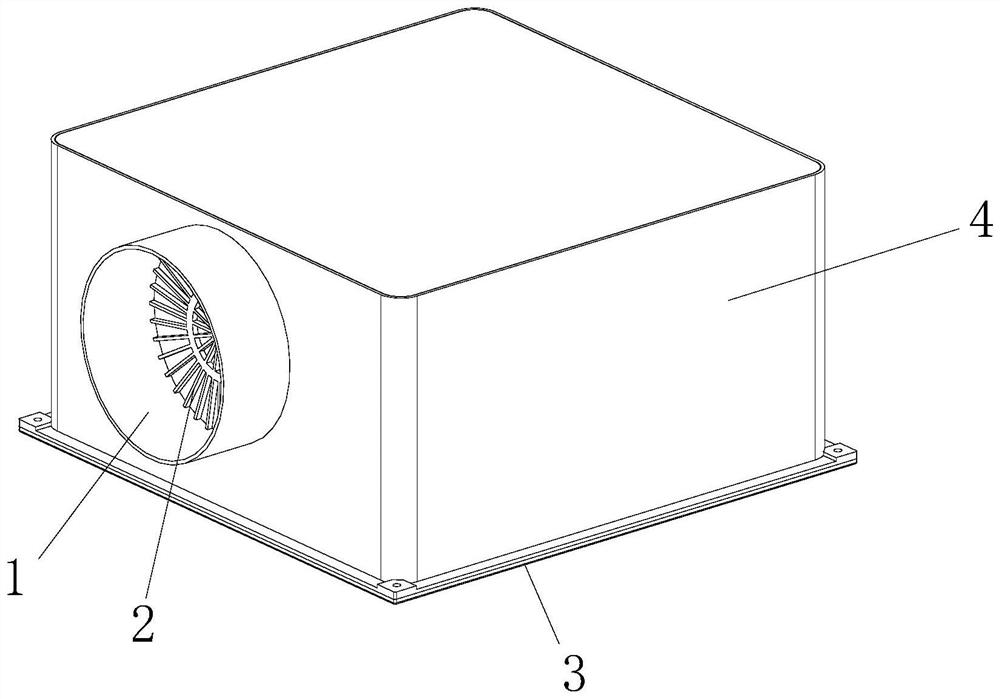
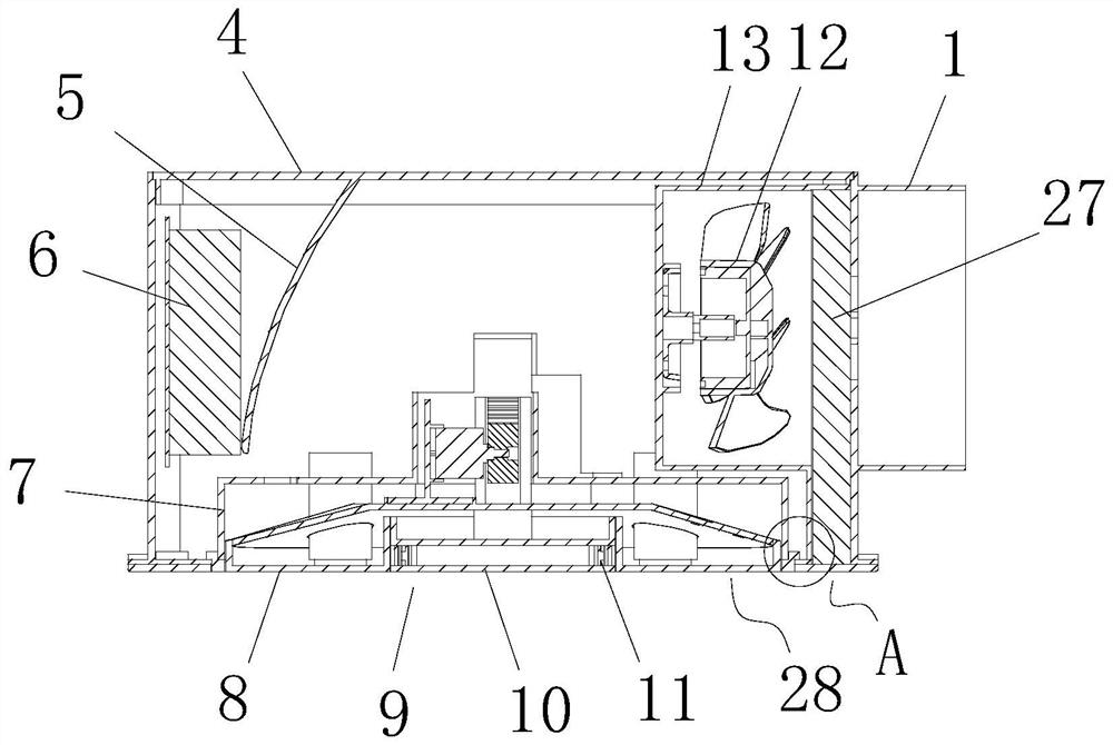
[0033] refer to Figure 1-8 , a kitchen range hood linkage exhaust air supply device, comprising a casing 4, the bottom end face of the casing 4 is integrally provided with a mounting plate 3, one side end face of the casing 4 is integrally provided with an upper air inlet and outlet frame 1, An annular screen frame 2 is installed in the upper inlet and outlet air frame 1, a control circuit board 6 is installed on the inner side wall of the outer casing 4, and an arc baffle 5 is arranged on one side of the control circuit board 6. The arc baffle 5 is fixedly connected to the inner top side wall of the casing 4, the bottom side wall of the casing 4 is integrally provided with an annular frame 7, and the annular frame 7 is installed with a lifting air inlet and outlet assembly 28, and the lifting air inlet and outlet assembly 28 is connected to the annular frame. A lower air inlet and outlet 16 is arranged between the 7, the upper side wall of the annular frame 7 is provided wit...

Embodiment 2

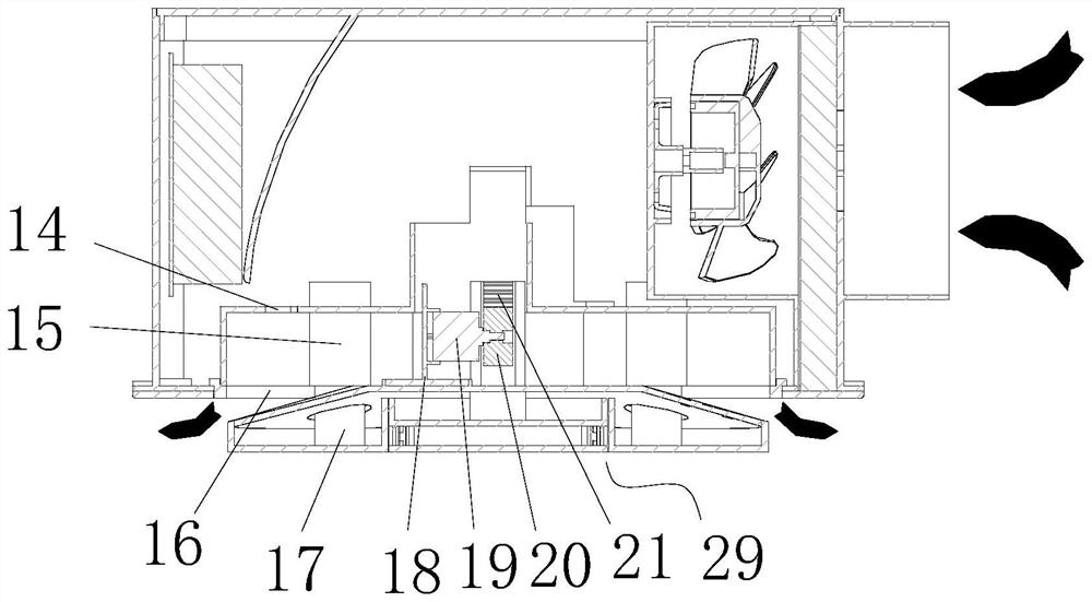
[0047] The difference between this embodiment and the above-mentioned embodiment is that a lifting disinfection assembly 29 is installed at the bottom of the lifting air inlet and outlet assembly 28 , the lifting disinfection assembly 29 includes a disinfection lamp installation frame 10 , and an annular groove is provided on the bottom end surface of the installation frame 8 9. The sterilizing lamp installation frame 10 is arranged in the annular groove 9, a plurality of ultraviolet sterilizing lamps 11 are installed on the outer end of the sterilizing lamp installation frame 10, and the upper end surface of the sterilizing lamp installation frame 10 is fixedly connected with a second lamp. Rack plate 21, a motor mounting seat 18 is fixed on the upper end surface of the mounting frame 8, a second motor 19 is mounted on the motor mounting seat 18, and the output end of the second motor 19 is fixedly connected with a second driving gear 20 , the second rack plate 21 is verticall...


PUM


Abstract

The linkage air exhausting and supplying device comprises a shell, a mounting plate is integrally arranged on the bottom end face of the shell, an upper air inlet and outlet frame is integrally arranged on the end face of one side of the shell, an annular screen frame is mounted in the upper air inlet and outlet frame, and a control circuit board is mounted on the inner side wall of the shell; an arc-shaped baffle is arranged on one side of the control circuit board, the arc-shaped baffle is fixedly connected with the side wall of the top in the shell, an annular frame is integrally arranged on the side wall of the bottom of the shell, and a lifting air inlet and outlet assembly is installed in the annular frame. The air supply and inlet device is provided for an existing range hood, fresh air is provided for cooking fume exhaust of a kitchen, cooking fume exhaust of the kitchen with large cooking fume and small space can be effectively achieved, it is guaranteed that air flow in the kitchen supplies micro-positive pressure, the fume exhaust effect is guaranteed, the internal protection and sealing effect is good, kitchen air and kitchen ware can be disinfected through the ultraviolet disinfection lamp, and the environment is protected. The practicability is high.

Description

technical field [0001] The invention relates to the technical field of kitchen utensils, in particular to a linkage exhaust air supply device for a kitchen range hood. Background technique [0002] The range hood is an electrical appliance in the home kitchen to absorb the fumes generated during cooking. It can not only fulfill the functional role well, but also have a decorative concept that integrates the modern kitchen layout. [0003] The original intention of research and development of the present invention is mainly due to the fact that the current Chinese food is mainly stir-fried, and the large fumes are harmful to the health of people who stay in the kitchen for a long time. Although the current hood products on the market have high suction (17-20m 3 / Hour). With the current residential kitchen area of ​​5 square meters and a floor height of 2.2 meters, the overall kitchen is only 11 meters. 3 The air can be exhausted by the range hood. In the later stage, due to...

Claims


Application Information

Patent Timeline
IPC IPC(8): F24C15/20F24F7/003F24F7/007F24F8/108F24F8/22
CPCF24C15/2021F24F7/003F24F7/007F24F8/108F24F8/22
Inventor 胡晨杨振宇王毅
Owner 小左(北京)科技有限公司
Why Eureka
Try Eureka