
Air cylinder with fixed locking and bearing pressure sharing functions

A load-bearing and pressure technology, which is applied in the field of cylinders with locking and fixing to share the load-bearing pressure, can solve the problems of cylinder stability damage, easy damage to cylinders, and reduce the contact stability of objects and cylinders, so as to reduce weighing pressure and improve stability. sex, stress-reducing effects

Inactive Publication Date: 2022-06-17
重庆达因纳美传动技术有限公司
View PDF0 Cites 0 Cited by
  • Summary
  • Abstract
  • Description
  • Claims
  • Application Information

AI Technical Summary

Problems solved by technology

[0002] After the cylinder supports the movement of the object, in order to support the object at this position, usually the movable end of the cylinder slides in the piston passage through the piston after receiving the weight of the object, and the external air pump is used to transport the gas through the air pump, and the pressure of the gas pushes the piston to use In order to achieve the function of supporting the object, during the long-term support of the cylinder, because there is no pressure sharing mechanism on the cylinder of the prior art, the cylinder directly bears the gravity of the object. Long-term support, the movable end of the cylinder is easily damaged, resulting in damage to the stability of the cylinder itself
[0003] In the prior art, when the cylinder is connected to the object, screws are usually used for fixing or direct contact. The former cannot turn the screw when the space is small and inconvenient to operate. The latter direct contact is not conducive to the connection between the cylinder and the object. Fixed, reduced stability of contact between object and cylinder

Method used


Image

  • Air cylinder with fixed locking and bearing pressure sharing functions
  • Air cylinder with fixed locking and bearing pressure sharing functions
  • Air cylinder with fixed locking and bearing pressure sharing functions

Examples


Embodiment Construction

[0027] The following description serves to disclose the invention to enable those skilled in the art to practice the invention. The preferred embodiments described below are given by way of example only, and other obvious modifications will occur to those skilled in the art.

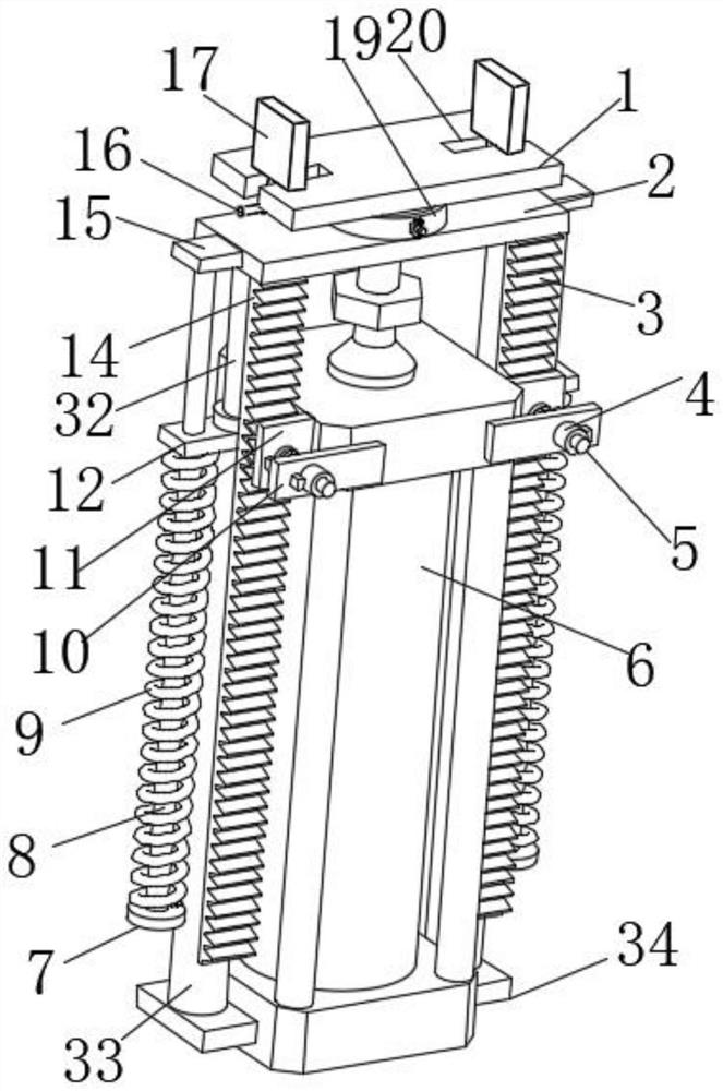
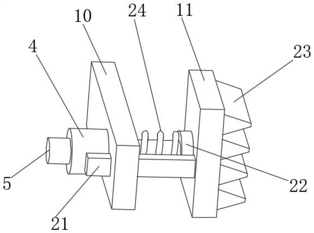
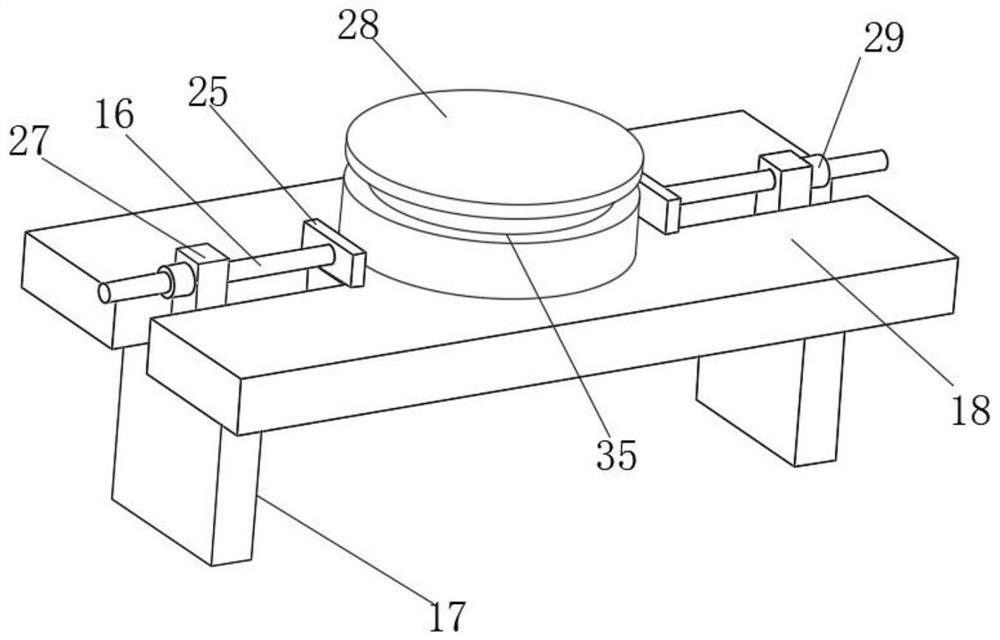
[0028] like Figure 1-8 The shown one has a locking position fixedly sharing the load-bearing pressure cylinder, including the cylinder body 6, the movable end of the cylinder body 6 is installed with a support plate 2 through screws, and the top of the support plate 2 is provided with an adjustable connection mechanism, the adjustable connection mechanism Including the movable plate 1, the bottom of the movable plate 1 and the top of the support plate 2 are connected by a rotating mechanism, the top of the movable plate 1 is provided with two long holes 20 extending to its two ends, and the bottom of the movable plate 1 is installed by screws Two lead screw positioning plates 25 are arranged, and the t...


PUM


Abstract

The invention relates to the technical field of air cylinders, in particular to an air cylinder with locking, fixing and bearing pressure sharing functions, which comprises an air cylinder body, a supporting plate is mounted at the movable end of the air cylinder body through screws, an adjustable connecting mechanism is arranged at the top of the supporting plate, and two bases are mounted at the bottom end of the air cylinder body through screws. And mounting pipe fittings are mounted at the tops of the two bases through screws. By arranging the first compression spring and the positioning mechanism, the supporting plate synchronously moves along with the movable end of the air cylinder, after the movable end of the air cylinder pushes a heavy object to move, the positioning mechanism can be operated to fix the position of the long strip block, the long strip block is used for sharing the weight borne by the movable end of the air cylinder after being fixed, the weighing pressure of the air cylinder is reduced, and the weighing efficiency is improved. And meanwhile, the first compression spring is used for reducing the weight borne by the supporting plate, the pressure borne by the movable end of the air cylinder is further reduced, and the air cylinder is protected.

Description

technical field [0001] The invention relates to the technical field of cylinders, in particular to a cylinder with a locking position, fixed load-bearing pressure sharing. Background technique [0002] After the cylinder supports the movement of the object, in order to support the object at this position, usually the movable end of the cylinder slides in the piston passage through the piston after receiving the weight of the object, and the external air pump is used to transport the gas through the air pump, and the pressure of the gas pushes the piston to use In order to achieve the function of supporting the object, during the long-term support of the cylinder, because there is no pressure sharing mechanism on the cylinder of the prior art, the cylinder directly bears the gravity of the object. Long-term support, the movable end of the cylinder is easily damaged, resulting in damage to the stability of the cylinder itself. [0003] In the prior art, when the cylinder is c...

Claims


Application Information

Patent Timeline
Patent Type & Authority Applications(China)
IPC IPC(8): B66F7/18B66F7/28
CPCB66F7/18B66F7/28
Inventor 刘义林薛中伟汪向阳肖尊军倪佳
Owner 重庆达因纳美传动技术有限公司
Learn More