Sliding block reversing jet flow tee joint and pulse micro-irrigation system
A tee and jet technology, which is applied in the fields of micro-irrigation system and its connecting tee, slider reversing jet tee and pulse micro-irrigation system, can solve problems such as pulse wave attenuation, and achieve easy processing, low manufacturing cost, The effect of simple element structure
- Summary
- Abstract
- Description
- Claims
- Application Information
AI Technical Summary
Problems solved by technology
Method used
Image
Examples
Embodiment 1
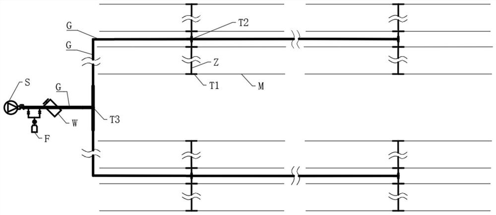
[0036] combined with figure 1 As shown, a slider reversing jet tee and pulse micro-irrigation system, including a water pump S, a fertilization device F, a filter device W, a main pipe G, a branch pipe Z, a capillary M, a jet pulse tee T, a capillary joint MP, Dripper D, valve V, branch pipe joint ZP, main pipe joint GP; it is characterized in that, the head end of the pulse micro-irrigation system is a water pump S, followed by a fertilization device F, followed by a filter device W, and then connected to the dry Pipe G, branch pipe Z, capillary M, and the tee of the pipeline are connected by jet pulse tee T; the combination of jet pulse tee T used in the pulse micro-irrigation system includes the following 7 schemes: 1st to 3rd The first scheme is to use only one of the capillary jet tee T1, the branch jet tee T2 or the trunk jet tee T3; the fourth to sixth schemes are to use the capillary jet tee T1, the branch jet tee T2 and the dry jet. Two of the tube jet tee T3 are com...
Embodiment 2
[0041] combined with Figure 1 to Figure 9 As shown, the basic structural features and implementation method of Embodiment 2 are similar to those of Embodiment 1, and the difference from Embodiment 1 lies in the structure of the jet flow reversing device 3 and the reversing method.
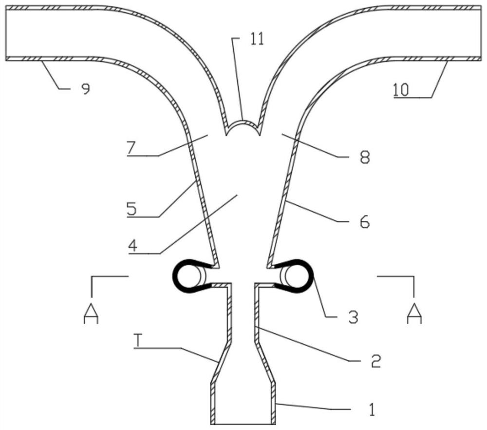
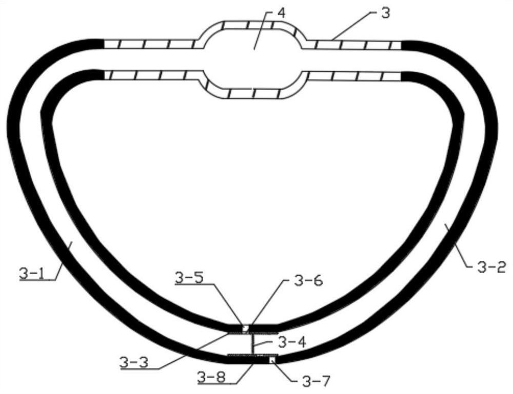
[0042] combined with Figure 5 As shown, the jet flow reversing device 3 is a negative pressure reversing device, including a left reversing channel 3-1 and a right reversing channel 3-2; The reversing channel 3-1 and the right reversing channel 3-2 are connected; the water flow enters the jet space 4 through the jet pipe 2 to form a jet flow, which produces a wall attachment effect; if the wall is attached to the left side wall 5 of the jet space first, it is entrained by the jet flow function to generate negative pressure in the left reversing channel 3-1; as the jet continues, the negative pressure will be transmitted to the right reversing channel 3-2, creating a pressure difference on both s...
Embodiment 3
[0044] combined with Figure 1 to Figure 9 As shown, the basic structural features and implementation method of Embodiment 3 are similar to those of Embodiment 1, and the difference from Embodiment 1 lies in the structure of the jet flow reversing device 3 and the reversing method.
[0045] combined with Image 6 As shown, the jet reversing device 3 is a hydraulic reversing device, including a left reversing channel 3-1 and a right reversing channel 3-2; a hole is opened on the left and right side walls of the top of the jet space 4, A hole is opened on the outer wall of the left water outlet pipe 9 and the right water outlet pipe 10, and the two holes on the same side are connected with a channel to form a left reversing channel 3-1 and a right reversing channel 3-2 respectively; The pipe 2 enters the jet space 4 to form a jet, and the wall effect is produced under the action of the jet entrainment; if the wall is first attached to the left side wall 5 of the jet space 4, it...
PUM
| Property | Measurement | Unit |
|---|---|---|
| Inlet diameter | aaaaa | aaaaa |
| Inlet diameter | aaaaa | aaaaa |
| Inlet diameter | aaaaa | aaaaa |
Abstract
Description
Claims
Application Information
 - R&D
- Intellectual Property
- Life Sciences
- Materials
- Tech Scout
- Unparalleled Data Quality
- Higher Quality Content
- 60% Fewer Hallucinations
Browse by: Latest US Patents, China's latest patents, Technical Efficacy Thesaurus, Application Domain, Technology Topic, Popular Technical Reports.
© 2025 PatSnap. All rights reserved.Legal|Privacy policy|Modern Slavery Act Transparency Statement|Sitemap|About US| Contact US: help@patsnap.com


