Aviation surge protection circuit with controllable discharge current

A discharge current and surge protection technology, which is applied in the field of power surge protection circuit, can solve problems such as occupying a large PCB space, difficult implementation, and poor power supply terminals of equipment, so as to reduce PCB occupation space, reduce circuit complexity, Circuit flexible and changeable effect

Pending Publication Date: 2022-06-07
SUZHOU SOFER ELECTRONICS & TECH CO LTD
View PDF0 Cites 1 Cited by
  • Summary
  • Abstract
  • Description
  • Claims
  • Application Information

AI Technical Summary

Problems solved by technology

[0003] The existing discharge current controllable aviation surge protection circuit has certain disadvantages in use. In the first way, using a large number of TVS devices will occupy a large amount of PCB space, and each device will be slightly different, that is, There is a short-circuit effect. Once a certain device fails, the entire TVS protection array will lose its function. At the same time, during TVS protection, the power supply is formed by a low-resistance loop through the TVS tube. Long-term surges will lead to long-term conduction. It is not good for the power supply end of the equipment; in the second way, it is sometimes difficult to find a device with a tolerance of 50V or more than 100V in some specific occasions; in the third way, each device is added Surge current-limiting resistors and TVS devices increase the cost and PCB space, but for high-current power devices, this method is more stringent for the selection of current-limiting resistors, and it will be more difficult to implement. Therefore, we propose a discharge current Controllable Aviation Surge Protection Circuit

Method used


Image

  • Aviation surge protection circuit with controllable discharge current
  • Aviation surge protection circuit with controllable discharge current
  • Aviation surge protection circuit with controllable discharge current

Examples


Embodiment

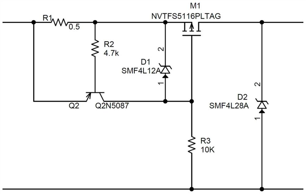
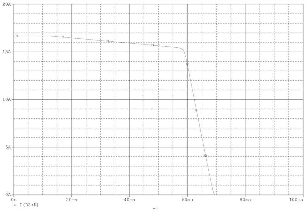
[0033] as Figure 3 、 4 as shown, Figure 3 It is the current curve of the no. 1 resistance R1 = 0.05 ohms, and the third resistance R3 = 4.7K ohms, flowing through diode D2;

[0034] Figure 4 is a voltage waveform diagram of both input and output;

[0035] As can be seen from the above two figures, this application meets the design requirements.

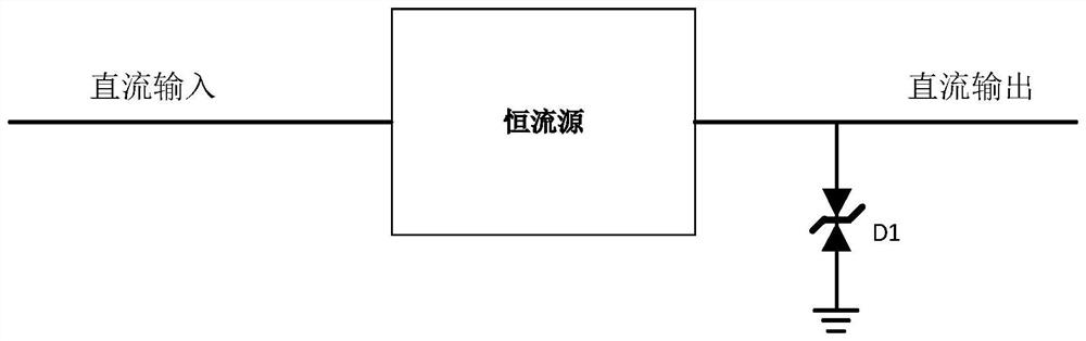
[0036]Working principle: The circuit of the present application is composed of two parts, one is a constant current source, one is a single ordinary TVS diode, the constant current source can suppress the discharge current of the TVS in the range of the TVS tube, set the relevant parameters of the constant current source, you can meet the current value of different TVS, the constant current source is composed of a MOSFET, a small power triode and a regulator, which are very easy to meet the 50V and 100V withstand voltage, but also relatively easy to meet the GJB and related temperature standards, MOSFET selection according to the current...


PUM


Abstract

The invention discloses a discharge current controllable aviation surge protection circuit, the circuit comprises a constant current source circuit and a common TVS diode circuit, the input end of the constant current source circuit is connected with a direct current input signal, the output end of the constant current source circuit outputs a direct current signal and is connected with the common TVS diode circuit, and the output end of the constant current source circuit is connected with the common TVS diode circuit. A TVS tube is arranged in the common TVS diode circuit, and the constant current source circuit suppresses the discharge current of the common TVS diode circuit within the bearing range of the TVS tube. According to the aviation surge protection circuit with the controllable discharge current, the problem of long-time surge can be solved without a large number of TVS devices and the design of withstanding more point voltage, surge protection of the whole circuit is completed through a general front end, and the aviation surge protection circuit with the controllable discharge current can meet the requirement of safety protection. A 50V or 100V TVS is added to the power supply input end of the whole circuit to absorb a 1.2 / 50u or 8 / 20us waveform conventional surge current, and a post-stage constant current source circuit is protected.

Description

Technical field [0001] The present invention relates to the field of power surge protection circuits for aviation equipment, in particular to a kind of aviation surge protection circuit with controllable discharge current. Background [0002] Discharge current controllable aviation surge protection circuit is a kind of aviation surge internal diode protection circuit, the actual working voltage in the standard is 29V, but the surge voltage is 50V, and the voltage of civil aviation equipment can be as high as 80 to 100V. Duration up to 82.5ms, the general TVS and varistors are usually used to suppress surges of about 1000us, so the conventional design has two ways, one is to use a large number of TVS devices to absorb energy, the other is to use a device that can withstand 50V or 100V input voltage as a working device, the third way is to add a small current limiting resistor and a separate TVS for each device, with the continuous development of science and technology, people's re...

Claims


Application Information

Patent Timeline
Patent Type & Authority Applications(China)
IPC IPC(8): H02H9/02
CPCH02H9/025Y02B20/30
Inventor 金宇华金海
Owner SUZHOU SOFER ELECTRONICS & TECH CO LTD
Why Eureka
Try Eureka