Feeding sealing and anti-blocking device and method for rotary equipment

An equipment and anti-blocking technology, applied in descaling devices, lighting and heating equipment, rotary drum furnaces, etc. Economic effect, the effect of preventing dust pollution and ensuring the smooth flow of materials

Pending Publication Date: 2022-06-07
HENAN ZHENGZHOU MINING MACHINERY
View PDF5 Cites 0 Cited by
  • Summary
  • Abstract
  • Description
  • Claims
  • Application Information

AI Technical Summary

Problems solved by technology

[0003] When dealing with viscous materials, the action of the flap valve is not flexible and cannot play the role of sealing
There will also be sticky material in the chute into the kiln. When there is too much sticky...

Method used


Image

  • Feeding sealing and anti-blocking device and method for rotary equipment
  • Feeding sealing and anti-blocking device and method for rotary equipment
  • Feeding sealing and anti-blocking device and method for rotary equipment

Examples


Embodiment 1

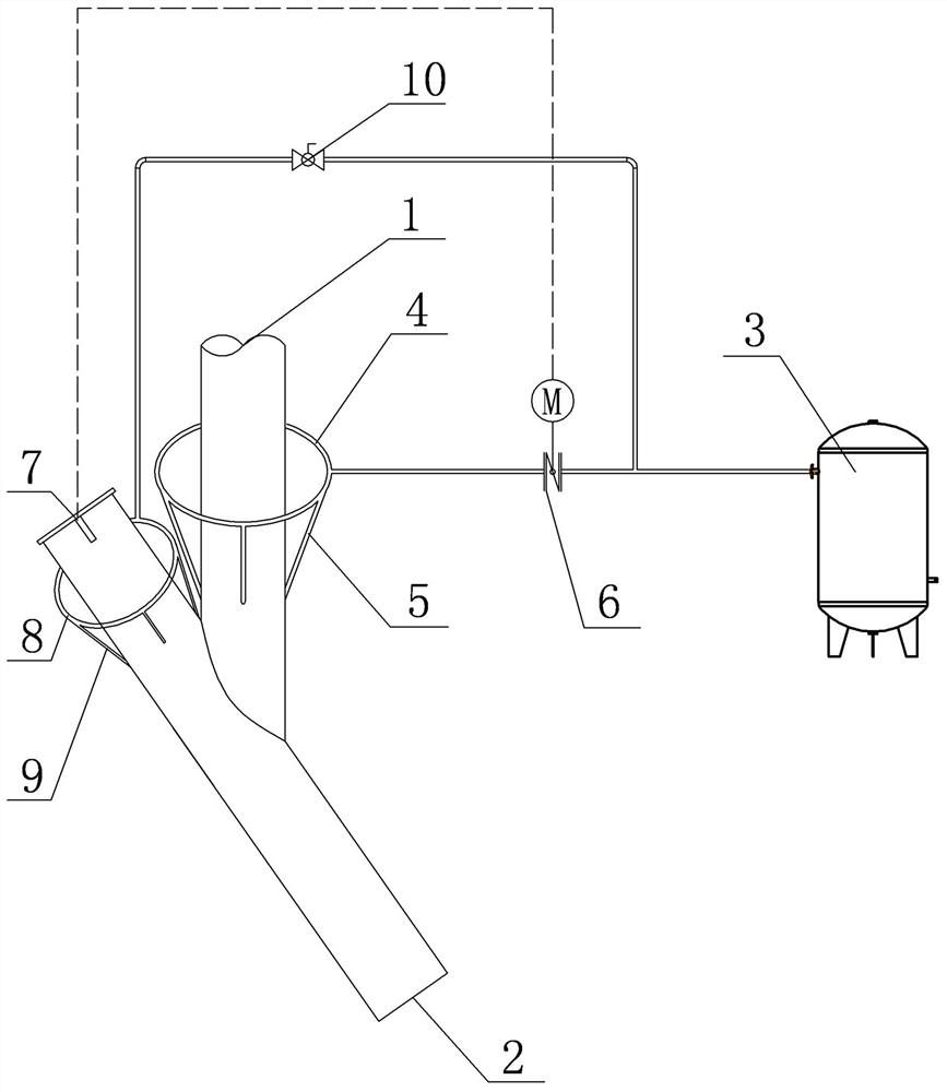
[0032] The material enters the device from the feed port 1 of the kiln chute, and leaves the device from the discharge port 2 of the kiln chute. The compressed air output from the compressed air storage tank 3 is divided into two paths, one for material purging, and the other for ultrasonic sensor purging.

[0033] In order to prevent the hot air of the rotary equipment from returning from the discharge port 2 to the feed port 1, and when the material accumulates in the kiln inlet chute, use compressed air to blow off the accumulated material, and set up a material purging pipeline. In the material purging pipeline, there are material purging loop pipe 4, material purging branch pipe 5 and electric regulating valve 6. The material purging ring pipe 4 is arranged around the vertical section of the kiln inlet chute. A plurality of material purging branch pipes 5 are evenly connected in the circumferential direction of the material purging ring pipe 4, and the material purging br...

Embodiment 2

[0037] Embodiment 2: This embodiment is basically the same as Embodiment 1, and the similarities will not be repeated. The difference is that the function can be cut and selected according to different usage conditions and cost requirements of the kiln chute, and the use occasions can be expanded. For example, if the material pollution is not serious, the ultrasonic sensor may not be installed to purge the pipeline.

[0038] Of course, the manual regulating valve 10 can also be changed to an electric control valve, which is selected according to the actual situation, and will not be described in detail.

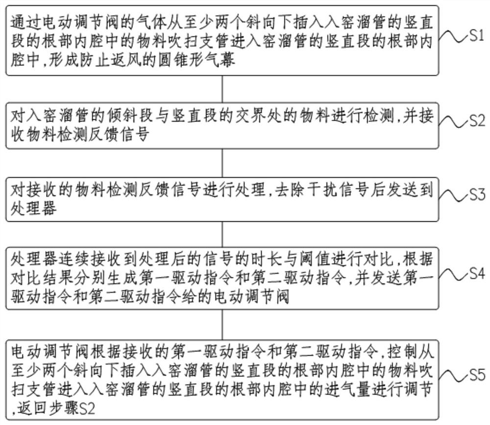
[0039] see Figure 1-Figure 3, the present application discloses a method for sealing and anti-blocking of the feed of the rotary equipment. In step S1, the gas passing through the electric regulating valve 6 is inserted into the inner cavity of the root of the vertical section of the kiln chute from at least two oblique downwards. The purging branch pipe 5 enters the inner ...


PUM


Abstract

The invention discloses a rotary equipment feeding sealing and anti-blocking device and method.The rotary equipment feeding sealing and anti-blocking device comprises a material purging pipeline and an ultrasonic sensor, the material purging pipeline comprises a material purging ring pipe, a material purging branch pipe and an electric control valve, the material purging ring pipe is arranged on the vertical section of a kiln entering elephant trunk in a surrounding mode, and the material purging branch pipe is arranged on the vertical section of the kiln entering elephant trunk in a surrounding mode; a plurality of material purging branch pipes are uniformly connected in the circumferential direction of the material purging ring pipe, the lower ends of the material purging branch pipes are obliquely inserted into the root part of the vertical section of the kiln entering articulated chute, and the material purging ring pipe is communicated with air supply equipment through an electric control valve and a connecting pipe; the ultrasonic sensor is arranged at the upper end part of an inclined pipe of the kiln-entering articulated chute; the ultrasonic sensor and the electric control valve are respectively connected with the controller; the air curtain is formed by jetting compressed air, and hot air is prevented from returning upwards from the kiln entering articulated chute; an ultrasonic sensor purging pipeline is arranged, so that the ultrasonic sensor is prevented from being polluted by dust, and the detection accuracy is improved.

Description

Technical field: [0001] The invention relates to a feed sealing technology for rotary equipment, in particular to a feed sealing and anti-blocking device and method for rotary equipment. Background technique: [0002] The kiln entry device of the rotary equipment is generally the kiln entry chute. In order to prevent the hot air from returning upward from the kiln entry chute, a flap valve is usually set to form a material seal to prevent back air. [0003] When dealing with viscous materials, the flap valve is inflexible and cannot function as a seal. There will also be sticky material in the kiln chute. When there is too much sticky material, it will even cause blockage, which will lead to material breakage in the production line, which requires manual feeding, which consumes a lot of manpower and time, and seriously affects the production process. Invention content: [0004] The technical problem to be solved by the present invention is to overcome the deficiencies of ...

Claims


Application Information

Patent Timeline
IPC IPC(8): F27B7/32F27B7/36F27B7/42F27D3/10F27D25/00
CPCF27B7/3205F27B7/36F27B7/42F27D3/10F27D25/008F27B2007/3282
Inventor 王晶臧营苏根华许文斌雷中明徐铭威高国峰郭栋
Owner HENAN ZHENGZHOU MINING MACHINERY
Why Eureka
Try Eureka