Eureka AIR delivers breakthrough ideas for toughest innovation challenges, trusted by R&D personnel around the world.

Control system and control method of automatic vibrating device

The technology of a vibrating device and a control system is applied to the control system and control field of an automatic vibrating device for a large-scale prefabricated reinforced concrete structure, which can solve the problems of high concrete construction quality requirements, large span, large volume, etc., so as to improve safety. and reliability, improved timeliness, compact structure

Pending Publication Date: 2022-06-03
HOHAI UNIV CHANGZHOU
View PDF0 Cites 3 Cited by
  • Summary
  • Abstract
  • Description
  • Claims
  • Application Information

AI Technical Summary

Problems solved by technology

[0002] Large prefabricated beams generally have large spans, large volumes, and high requirements for concrete construction quality. The automatic vibration of concrete is a key link to realize the automation of construction machinery. At present, although there are many types of vibration devices in the field of engineering technology, they are basically The vibrating rod is manually operated to carry out the vibrating work. The control system and control method for the large-scale prefabricated reinforced concrete structure vibrating device have not been developed, and the displacement of the walking frame, the rotation of the wheel, the adjustment of the angle of the mechanical arm and the vibration cannot be realized. The control of key components such as rod vibrators is not conducive to the development of reinforced concrete vibrators in the direction of automation

Method used

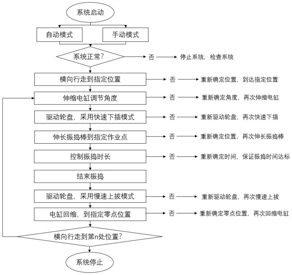

Image

  • Control system and control method of automatic vibrating device
  • Control system and control method of automatic vibrating device
  • Control system and control method of automatic vibrating device

Examples


Embodiment Construction

[0022] The technical solutions in the embodiments of the present invention will be clearly and completely described below with reference to the accompanying drawings in the embodiments of the present invention. Obviously, the described embodiments are only a part of the embodiments of the present invention, but not all of the embodiments. Based on the embodiments of the present invention, all other embodiments obtained by those of ordinary skill in the art without creative efforts shall fall within the protection scope of the present invention.

[0023] The vibrating device used for the control of the control system of the present invention may include the following structures:

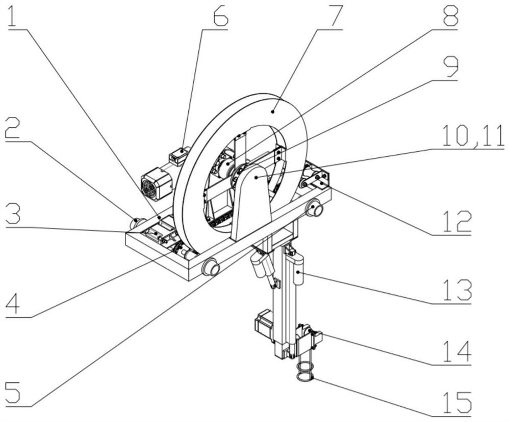
like image 3 , Figure 4 as well as Figure 7 As shown, the vibrating device in the present invention includes a vibrating car body, a vibrating rod, a storage tube mechanism arranged on the vibrating car body, and a counter-rolling mechanism 12; The vibrating executive component; the vibrating car...


PUM


Abstract

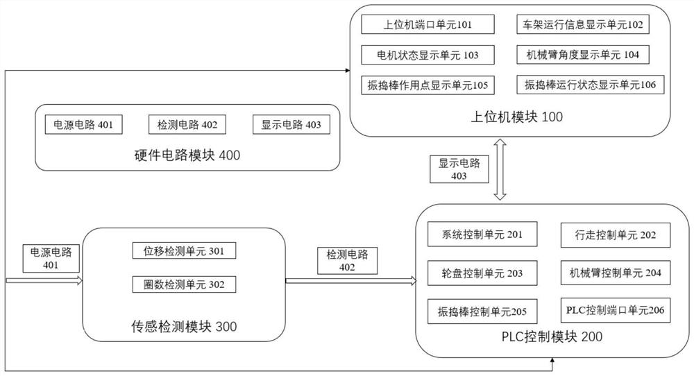
The invention relates to the technical field of building machinery, and discloses a control system and method of an automatic vibrating device, and the system comprises an upper computer module, a PLC control module, and a sensing detection module. The data output end of the upper computer module is connected with the communication port of the PLC control module, and the upper computer module is used for controlling the input of the PLC control system; the PLC control module is used for receiving a control signal of the upper computer module and then identifying the signal; the output end of the sensing detection module is connected with the input end of the PLC control module, and the sensing detection module is used for detecting the displacement of the walking frame, the descending height of the vibrating rod, the descending circle number of the vibrating rod and the adjusting angle of the mechanical arm in real time. The prefabricated reinforced concrete vibrating device has the beneficial effects that the prefabricated reinforced concrete vibrating device is used for automatic vibrating work of prefabricated reinforced concrete, and automatic and standardized operation of vibrating construction of a reinforced concrete structure can be achieved through the vibrating device.

Description

technical field [0001] The invention belongs to the technical field of automatic control of construction machinery, relates to a control system and a control method of an automatic vibrating device, and in particular relates to a control system and a control method of an automatic vibrating device for a large prefabricated reinforced concrete structure. Background technique [0002] Large-scale prefabricated beams generally have large spans, large volumes and high requirements for concrete construction quality. Automatic vibrating of concrete is a key link in the automation of construction machinery. At present, although there are many types of vibrating devices in the field of engineering technology, they are basically The vibrating rod is manually operated to perform the vibrating work. The control system and control method for the large-scale prefabricated reinforced concrete structure vibrating device have not yet been developed. The control of key components such as rod...

Claims


Application Information

Patent Timeline
IPC IPC(8): G05B19/05
CPCG05B19/054G05B2219/1103Y02P90/02
Inventor 张磊高远孙娟张昊
Owner HOHAI UNIV CHANGZHOU
Why Eureka
Eureka Blog
Learn More