
Pipeline mounting bracket capable of saving building floor height

A pipeline installation and building layer technology, applied in the direction of pipeline supports, sustainable buildings, pipes/pipe joints/fittings, etc., can solve the problems of occupying usable building space, wasting building space, occupying usable space, etc.

Pending Publication Date: 2022-05-31
王皇凰
View PDF3 Cites 1 Cited by
  • Summary
  • Abstract
  • Description
  • Claims
  • Application Information

AI Technical Summary

Problems solved by technology

Another example is the patent No. 202121790924.8, and the existing patent titled "A Finished Bracket for Indoor Construction Pipelines with Adjustable Pipe Clamps" includes the following technical solutions: the support plate is suspended by the support rod and the sleeve column, and the support plate There is a fixed screw on the top, the bottom beam is movably connected to the screw, and the pipe clamp for clamping the pipeline is fixed on the ground beam. When in use, the pipe clamp, bottom beam and support plate under the jurisdiction will occupy the use space ; Another example is that the patent No. is 201920917351.7, and the existing patent titled "An electromechanical pipeline installation hanger that is easy to adjust" includes the following technical solutions: the bottom of the bracket is fixedly connected to the top of the cantilever, and the surface of the cantilever is movable. Sliding seat, the top of the sliding seat is equipped with a pipe clamp. During use, the pipeline is located vertically above the sliding seat and the cantilever, and the sliding seat and cantilever located below the pipeline will occupy the usable space of the building
[0003]Therefore, the pipeline lifting bracket in the prior art will have part of the structure located under the pipeline during use, and this part of the structure will cause the occupation of valuable building floors High, wastes building space

Method used


Image

  • Pipeline mounting bracket capable of saving building floor height
  • Pipeline mounting bracket capable of saving building floor height
  • Pipeline mounting bracket capable of saving building floor height

Examples


Embodiment 1

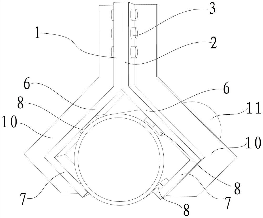
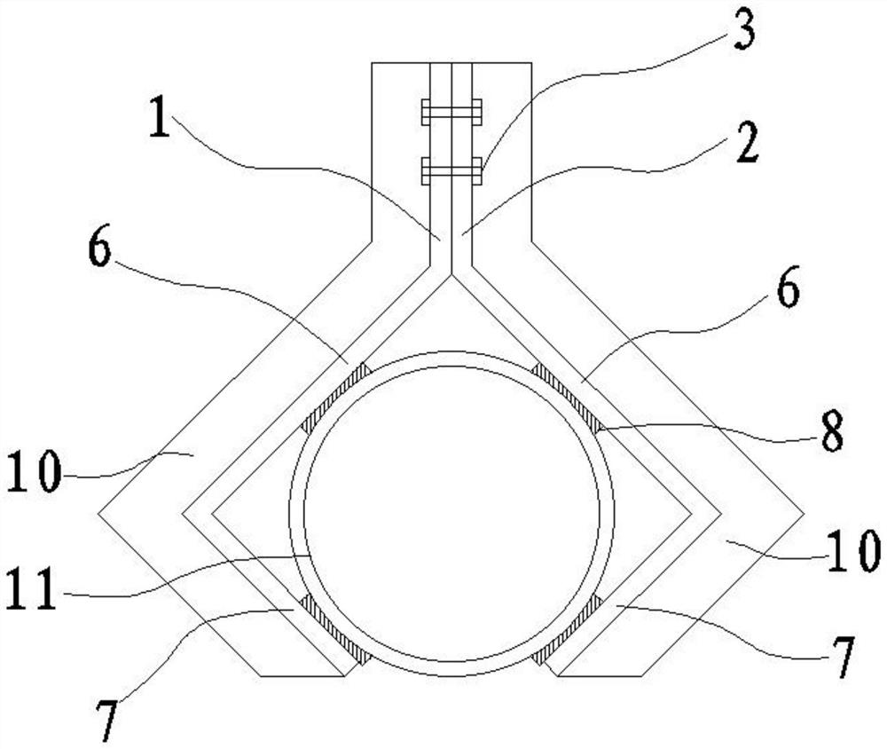
[0037] Such as figure 1 , figure 2 As shown, in this embodiment, a connecting frame A1 and a connecting frame B2 are included, and the connecting frame A1 and the connecting frame B2 are fixedly connected by a connecting fixture 3. In this embodiment, the connecting fixture 3 adopts Bolts and nuts are convenient for the installation and disassembly of the connecting frame A1 and the connecting frame B2, and the tops of the connecting frame A1 and the connecting frame B2 are fixedly connected with the building structure by means of a ceiling bracket or an anti-seismic bracket (by a ceiling bracket or The connection between the anti-seismic support and the building is a conventional technical means in the art, and its specific structure is not described in detail here), the bottom end of the connecting frame A1 is fixedly provided with a pipe clamp A4, and the bottom end of the connecting frame B2 is fixed A pipe clamp B5 is provided, the connecting frame A1 and the pipe clamp...

Embodiment 2

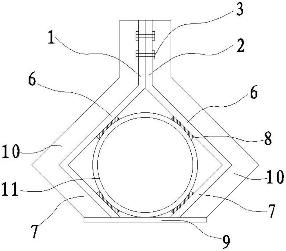
[0043] Such as image 3 As shown, when the pipeline is heavy, in order to improve the clamping strength of the pipeline 11, this embodiment adds the following technical solution on the basis of the third embodiment: the bottom ends of the pipe clamp A4 and the pipe clamp B5 pass through the reinforcement connector 9 Fixed connection, that is, the bottom ends of the two second holding sections 7 are fixedly connected through the reinforcement connector 9 to improve the clamping strength of the pipeline 11. Specifically, the reinforcement connector 9 can use a connecting plate or a linear steel The connecting plate can be fixedly connected with the pipe clamp A4 and the pipe clamp B5 by welding, bolting or riveting, and the pipe clamp A4 and the pipe clamp B5 can be fixedly connected through the reinforced connecting frame, so as to limit the pipe clamp A4 and the pipe clamp B5. The clamp B5 is opened to both sides to ensure the strength and stability of clamping the pipeline 11...

Embodiment 3

[0045] Such as Figure 4 As shown, in this embodiment, a connecting frame A1 and a connecting frame B2 are included, and the connecting frame A1 and the connecting frame B2 are fixedly connected by a connecting fixture 3. In this embodiment, the connecting fixture 3 adopts Bolts and nuts are convenient for the installation and disassembly of the connecting frame A1 and the connecting frame B2, and the tops of the connecting frame A1 and the connecting frame B2 are fixedly connected with the building structure by means of a ceiling bracket or an anti-seismic bracket (by a ceiling bracket or The connection between the anti-seismic support and the building is a conventional technical means in the art, and its specific structure is not described in detail here), the bottom end of the connecting frame A1 is fixedly provided with a pipe clamp A4, and the bottom end of the connecting frame B2 is fixed A pipe clamp B5 is provided, the connecting frame A1 and the pipe clamp A4 are inte...


PUM


Abstract

The invention relates to the technical field of building supports, in particular to a pipeline mounting support capable of saving building floor height. Comprising a connecting frame A and a connecting frame B, the connecting frame A and the connecting frame B are fixedly connected through a connecting fixing piece, a pipe clamp A is fixedly arranged at the bottom end of the connecting frame A, a pipe clamp B is fixedly arranged at the bottom end of the connecting frame B, and the pipe clamp A and the pipe clamp B are used for clamping a pipeline. And the bottom ends of the pipe clamp A and the pipe clamp B are higher than the bottom of the pipeline clamped by the pipe clamp A and the pipe clamp B or are flush with the bottom of the pipeline clamped by the pipe clamp A and the pipe clamp B. The pipeline support has the beneficial effects that the pipeline is clamped and supported in a left-right clamping mode, the bottom ends of the pipe clamp A and the pipe clamp B are higher than or flush with the bottom of the pipeline, the pipeline support is prevented from occupying the building floor height below the pipeline, the utilization rate of the internal space of a building is increased, and waste of the building space is reduced.

Description

technical field [0001] The invention relates to the technical field of building brackets, in particular to a pipeline installation bracket which saves the building floor height. Background technique [0002] There are structures and various equipment in the architectural space, and the space that can be used by the building is only after the structure and equipment are removed. In civil buildings and many industrial buildings, the installation of pipelines such as water pipes, wiring pipes, air-conditioning and heating ducts usually requires the use of hanging brackets to support the pipelines, and the setting of the lifting brackets used to support the pipelines usually takes up a certain amount of building space. The hoisting bracket in the prior art is usually used to fix the pipe support at the bottom of more than two cantilevers, and then the pipeline is arranged on the pipe support, and the pipeline is supported by the pipe support. After the existing hoisting bracket ...

Claims


Application Information

Patent Timeline
Patent Type & Authority Applications(China)
IPC IPC(8): F16L3/10F16L3/11
CPCF16L3/1033F16L3/1066F16L3/11Y02B30/00
Inventor 王皇凰
Owner 王皇凰
Learn More