Gearbox lubricating and cooling system and low-temperature starting method thereof
A lubricating cooling and gear box technology, applied in the direction of gear lubrication/cooling, lubricating parts, engine lubrication, etc., can solve the problems of low preheating efficiency, high energy, high energy consumption, improve preheating efficiency and slow heat conduction. , the effect of increasing the heating rate
- Summary
- Abstract
- Description
- Claims
- Application Information
AI Technical Summary
Problems solved by technology
Method used
Image
Examples
Embodiment 1
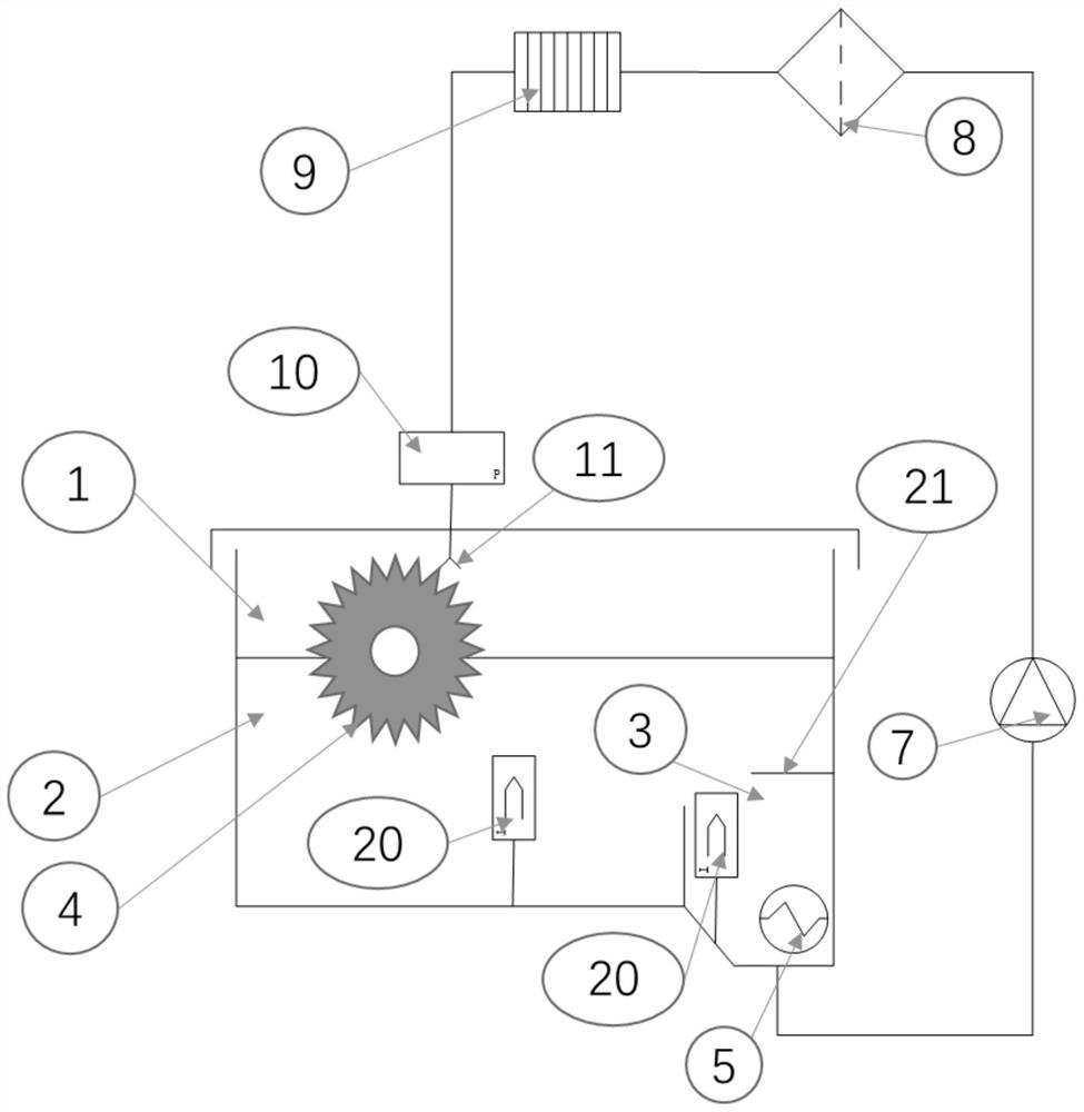
[0052] Such as figure 1 As shown, this embodiment proposes a gearbox lubrication and cooling system, including:
[0053] The first partition device 21, the first partition device 21 is arranged in the gear box 1, and divides the oil chamber of the gear box 1 into at least two sub-oil pools communicating with each other; if the gear box 1 has Two sub-oil pools are respectively the first sub-oil pool 2 and the second sub-oil pool 3, wherein the lubricating oil flows into the first sub-oil pool 2 after passing through the transmission structure 4; if the gearbox 1 has More than two sub-oil pools, respectively the first sub-oil pool 2 and the first intermediate oil pool, the second sub-oil pool 3, the first sub-oil pool 2 and the second sub-oil pool 3, the first sub-oil pool The oil pool 2 and the second sub-oil pool 3 are respectively located on both sides of the first middle oil pool, wherein the lubricating oil flows into the first sub-oil pool 2 after passing through the tran...
Embodiment 2
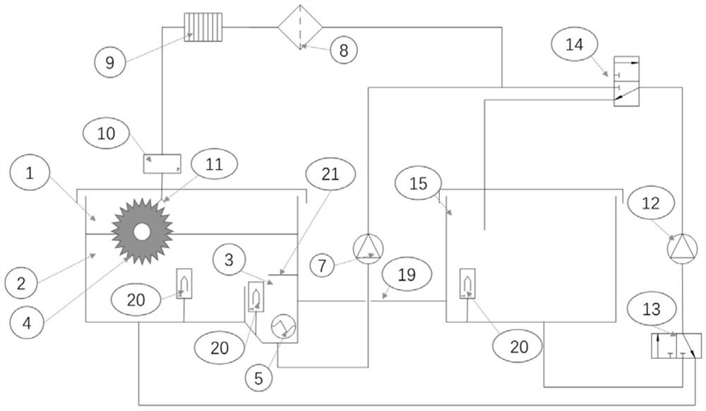
[0064] On the basis of the first embodiment above, in this embodiment, as figure 2 and Figure 2a As shown, the gear box 1 has an external oil tank 15, the oil cavity of the external oil tank 15 is connected to the second sub-oil pool 3 through a communication pipe 19, and the lubricating oil can be used in the first sub-oil pool 2 and the second sub-oil pool. Two sub-oil pools 3 and 15 external oil tanks flow.
[0065] On the basis of the first embodiment above, in this embodiment, the gearbox lubrication and cooling system further includes:
[0066] The second oil pump 12, the input end of the second oil pump 12 is connected to the first sub-oil pool 2 through the first multi-way valve 13, and the output end of the second oil pump 12 is connected to the first sub-oil pool 2 through the second multi-way valve 14. The external oil tank 15 is connected; the first sub-oil pool 2 is connected to the first multi-way valve 13, the second oil pump 12, the second multi-way valve 1...
Embodiment 3
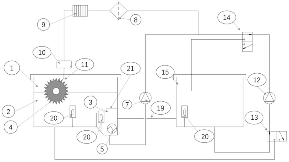
[0077] On the basis of the second embodiment above, in this embodiment, as image 3 and Figure 3a , Figure 3b As shown, the gearbox lubrication and cooling system also includes:
[0078] The second separation device 17, the second separation device 17 is arranged in the external oil tank 15, and divides the oil chamber of the external oil tank 15 into at least two sub-oil pools that communicate with each other; if the external The oil tank 15 has two sub-oil pools, which are then recorded as the third sub-oil pool 18 and the fourth sub-oil pool 16, wherein the third sub-oil pool 18 is connected with the second sub-oil pool 3 through a communication pipe 19, and the lubricating oil It can flow between the first sub-oil pool 2 and the fourth sub-oil pool 16; if the external oil tank 15 has more than two sub-oil pools, it is recorded as the second middle oil pool and the third sub-oil pool 18, the third sub-oil pool Four sub-oil pools 16, wherein the third sub-oil pool 18 an...
PUM
 Abstract
Description
Claims
Application Information
 - R&D
- Intellectual Property
- Life Sciences
- Materials
- Tech Scout
- Unparalleled Data Quality
- Higher Quality Content
- 60% Fewer Hallucinations
Browse by: Latest US Patents, China's latest patents, Technical Efficacy Thesaurus, Application Domain, Technology Topic, Popular Technical Reports.
© 2025 PatSnap. All rights reserved.Legal|Privacy policy|Modern Slavery Act Transparency Statement|Sitemap|About US| Contact US: help@patsnap.com


