Construction method of underground continuous pouring concrete pile wall

A technology of pouring concrete and construction method, applied in sheet pile wall, excavation, foundation structure engineering and other directions, can solve the problems of low efficiency, long construction period and high cost, and achieve the effect of simple construction process, low construction cost and increased cost

Pending Publication Date: 2022-05-31
邱树贵
View PDF0 Cites 0 Cited by
  • Summary
  • Abstract
  • Description
  • Claims
  • Application Information

AI Technical Summary

Problems solved by technology

However, the construction speed is extremely slow, the construction is difficult, the efficiency is low, the cost is high, and it is not continuous pouring concrete, so it is not suitable for construction under rock geological conditions
[0007] 4. Pile driving around the foundation pit: that is, to build a cement mixing pile waterstop wall outside the mud retaining pile pile. The construction period is long and the cost is high. The waterstop effect is affected by geological conditions, and the waterstop effect is poor. The construction of the pebble layer is difficult, and the water-stop effect is not good

Method used


Image

  • Construction method of underground continuous pouring concrete pile wall
  • Construction method of underground continuous pouring concrete pile wall
  • Construction method of underground continuous pouring concrete pile wall

Examples


specific Embodiment approach 1

[0036] Specific implementation one: as Figure 1-Figure 12 As shown, the present embodiment discloses a construction method for an underground continuous cast-in-place concrete pile wall, and the method includes the following steps:

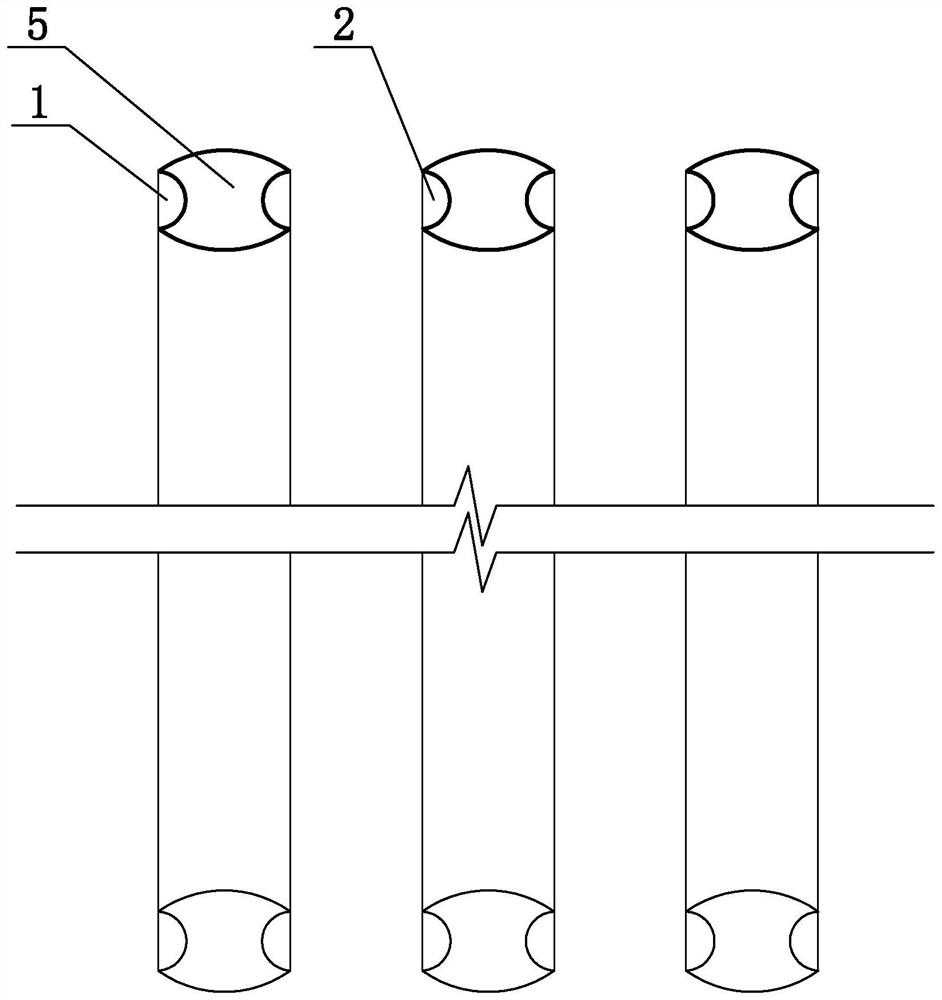
[0037] Step 1: Use a drilling rig to drill multiple A pile holes to the design depth. The multiple A pile holes are sequentially defined as A1 pile holes 1 to An pile holes from the head A pile hole to the end A pile hole, and n is divided by zero A natural number other than ; and fill all A pile holes with mud;

[0038] Step 2: First prepare a plurality of steel cylinder models 5, each steel cylinder model 5 is composed of two convex arc side walls 5-1 and two concave arc side walls 5-2, the two convex arc side walls The wall 5-1 and the two concave arc side walls 5-2 are respectively arranged symmetrically, and one end of the two convex arc side walls 5-1 on the same side is connected with both ends of the concave arc side wall 5-2; , put the...


PUM


Abstract

The invention discloses a construction method of an underground continuous pouring concrete pile wall, and belongs to the technical field of building foundation pit supporting. Drilling a plurality of A pile holes by using a drilling machine and filling the A pile holes with slurry; steel cylinder models are placed in all the A pile holes; a B1 pile hole is drilled between the A1 pile hole and the A2 pile hole to the designed depth, a B2 pile hole is drilled between the A2 pile hole and the A3 pile hole to the designed depth, slurry is injected into the B1 pile hole and the B2 pile hole, then the steel cylinder model in the A1 pile hole is pulled out, a steel circular protection cylinder is placed in the A1 pile hole, then the steel cylinder model in the A2 pile hole is pulled out, then the steel circular protection cylinder is placed in the A2 pile hole, and so on, and the pile hole is formed. Until the last steel circular pile casing is put into the An pile hole; and after concrete is poured into the B1 pile hole, a reinforcement cage is placed in the A1 pile hole and concrete is poured into the A1 pile hole, the steel protection cylinder in the A1 pile hole is pulled out, the concrete of the A1 pile and the B1 pile is connected into a whole before solidification, and the like, until overall construction of the concrete pile wall is completed. The construction method is used for construction of the underground continuous pouring concrete pile wall.

Description

technical field [0001] The invention belongs to the technical field of foundation pit support for building foundations, and in particular relates to a construction method for an underground continuous cast-in-place concrete pile wall. Background technique [0002] At present, my country adopts the following four construction methods for foundation pit support in the construction field: [0003] 1. Rotary spray reinforcement between piles: that is, the method of driving piles around the building, protecting the walls of the concrete cast-in-place piles, and spraying the cement slurry between the piles after the pile construction is completed to strengthen the soil and stop the water. This method has slow construction speed, long construction period, high cost, and poor water-stopping effect. Especially in the geological conditions of sand layer and pebble layer, it is easy to leak water and cannot be constructed in rock layer. [0004] 2. Construction of concrete occlusal pi...

Claims


Application Information

Patent Timeline
IPC IPC(8): E02D17/04E02D5/18E02D5/38
CPCE02D17/04E02D5/385E02D5/187
Inventor 邱树贵
Owner 邱树贵
Why Eureka
Try Eureka