
Non-vision field imaging device and method

An imaging method and field of view technology, which is applied in the field of non-line-of-sight imaging, can solve problems such as limitations, and achieve the effect of high tolerance and improved detection sensitivity

Pending Publication Date: 2022-05-27
陈宇翱 +7
View PDF0 Cites 0 Cited by
  • Summary
  • Abstract
  • Description
  • Claims
  • Application Information

AI Technical Summary

Problems solved by technology

However, limited by the time precision that electronic devices can achieve (about tens of picoseconds), the imaging precision of this type of system is limited to centimeters

Method used


Image

  • Non-vision field imaging device and method
  • Non-vision field imaging device and method
  • Non-vision field imaging device and method

Examples


Embodiment Construction

[0037] Hereinafter, embodiments of the present disclosure will be described with reference to the accompanying drawings. It should be understood, however, that these descriptions are exemplary only, and are not intended to limit the scope of the present disclosure. In the following detailed description, for convenience of explanation, numerous specific details are set forth in order to provide a thorough understanding of the embodiments of the present disclosure. It will be apparent, however, that one or more embodiments may be practiced without these specific details. Also, in the following description, descriptions of well-known structures and techniques are omitted to avoid unnecessarily obscuring the concepts of the present disclosure.

[0038] The terminology used herein is for the purpose of describing particular embodiments only and is not intended to limit the present disclosure. The terms "comprising", "comprising" and the like as used herein indicate the presence o...


PUM


Abstract

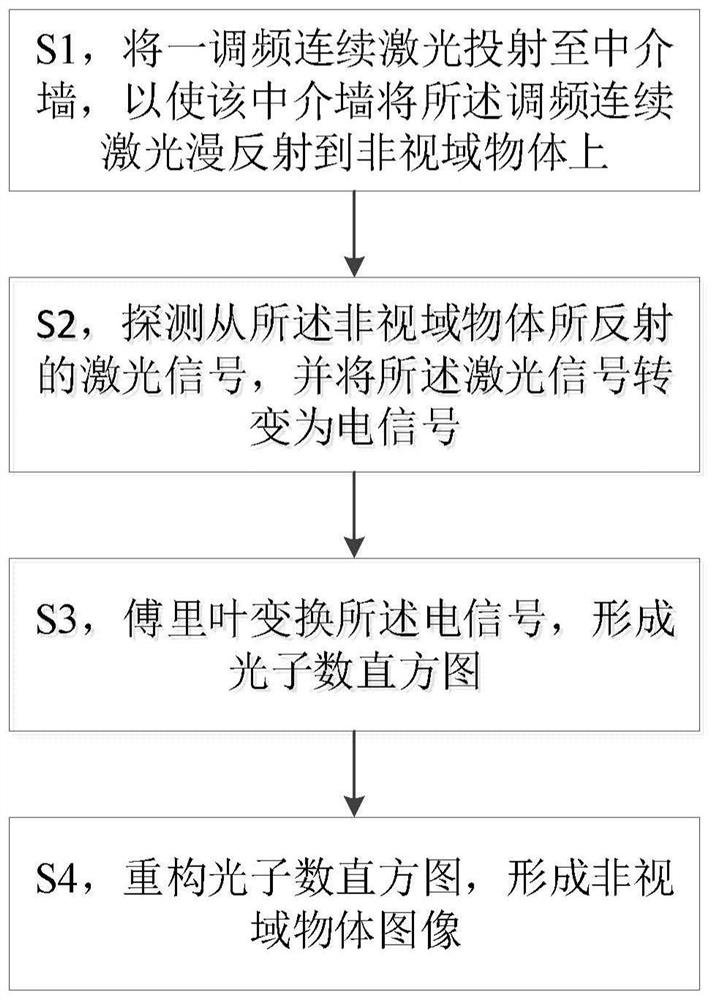
The invention provides a non-vision-field imaging method, which comprises the following steps of: S1, projecting frequency modulation continuous laser to a medium wall, so that the medium wall reflects the frequency modulation continuous laser to a non-vision-field object, and attenuating another frequency modulation continuous laser; s2, detecting a laser signal reflected from a non-vision field object and another laser signal after attenuation, mixing the laser signal with the another laser signal to form a mixed signal, and converting the mixed signal into an electric signal; s3, performing Fourier transform on the electric signal to form a photon number histogram; and S4, reconstructing the photon number histogram to form a non-vision field object image. According to the non-vision-field imaging method disclosed by the invention, frequency modulation continuous wave imaging is innovatively introduced into the non-vision-field imaging field, and compared with a traditional time-domain non-vision-field imaging system, the system can realize non-vision-field imaging precision exceeding a time-domain system by utilizing a frequency modulation laser with a relatively large frequency modulation range; and millimeter-level and even micron-level non-vision-field imaging precision is realized.

Description

technical field [0001] The present disclosure relates to the field of non-view-of-sight imaging, and in particular, to a non-view-of-sight imaging device and method. Background technique [0002] Optical non-line-of-sight imaging is a novel imaging concept. Since light propagates in a straight line in the same homogeneous medium, generally speaking, the object of optical imaging is the target scene within the line of sight of the human eye or the field of view of the imaging device. Due to the limited field of view, a large amount of visual information outside the field of view cannot be captured in nature. However, optical non-horizontal imaging technology can take pictures of objects hidden outside the line of sight through the diffuse reflection of the intermediate surface, and perform "wall viewing". Thus, it breaks through the limit of traditional optical imaging and expands the imaging ability of human beings. It is foreseeable that in the near future, non-horizonta...

Claims


Application Information

Patent Timeline
Patent Type & Authority Applications(China)
IPC IPC(8): G01S17/89G01S7/481
CPCG01S17/89G01S7/481
Inventor 徐飞虎黄鑫黎正平潘建伟
Owner 陈宇翱
Learn More