Evacuated collector tube
A vacuum heat collection tube and vacuum technology, applied in the field of heat collection tubes, can solve problems such as broken glass tubes and large temperature differences, and achieve the effect of reducing the heat loss coefficient
- Summary
- Abstract
- Description
- Claims
- Application Information
AI Technical Summary
Problems solved by technology
Method used
Image
Examples
Embodiment 1
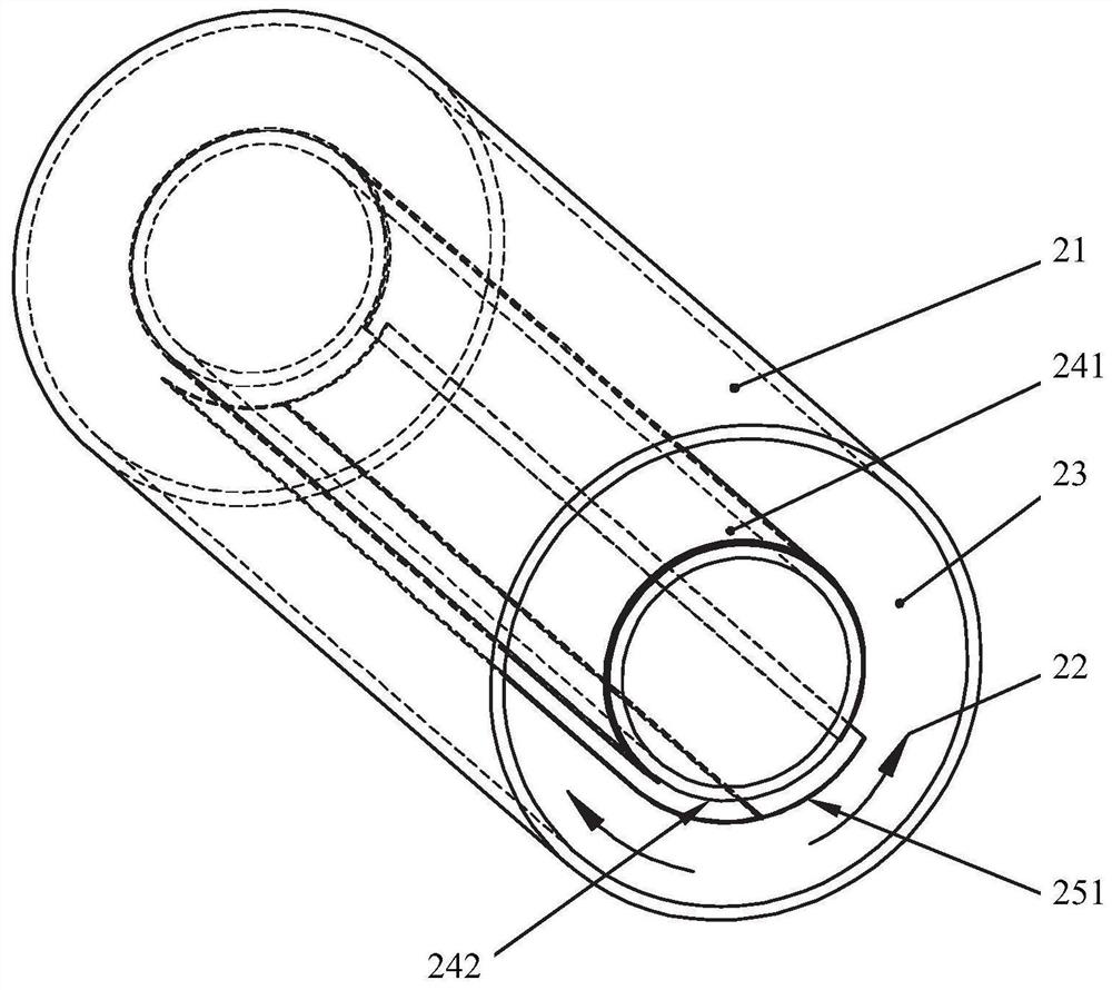
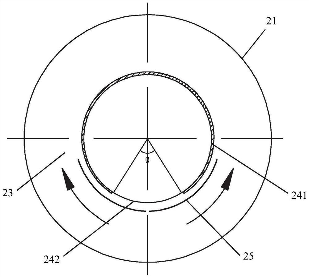
[0073] Figures 2(1) to 2(4) The structure of the first preferred embodiment of this case is given.
[0074] The vacuum heat collecting tube in this embodiment 1 includes a vacuum outer tube 21, a vacuum inner tube 22, a vacuum interlayer 23 between the two, and a solar heat collecting layer 24 on the outer surface of the vacuum inner tube 22, and the heat collecting layer 24 is Selective absorption coating on the outer wall of the vacuum inner tube 22 .
[0075] From the cross-sectional view of FIG. 2(2), the heat collecting layer 24 does not completely cover the outer wall of the vacuum inner tube 22, but adopts partial coverage. The coating area 241 and the non-coating area 242 are axially arranged along the outer wall of the vacuum inner tube to form two A sector-shaped area, wherein the central angle corresponding to the sector-shaped area of the non-coated area 242 is shown as θ, and the central angle corresponding to the sector-shaped area of the coated area 241 is...
Embodiment 2
[0084] Figures 3(1) to 3(4) The structure of the second preferred embodiment of this case is given.
[0085] The basic structure of this embodiment is similar to that of Embodiment 1. The vacuum heat collecting tube includes a vacuum outer tube 21, a vacuum inner tube 22, a vacuum interlayer 23 between the two, and a solar heat collecting layer 24 on the outer surface of the vacuum inner tube 22. The heat collecting layer 24 includes two fan-shaped coating areas 241 and a non-coating area 242 .
[0086] The difference from Embodiment 1 is that a reflection unit 26 fixed by a bracket is added in the vacuum interlayer 23 . As shown in the figure, the two ends of the reflection unit 26 are respectively arranged on the outer side of the vacuum inner tube 22 and the inner side of the vacuum outer tube 21 , so as to separate the vacuum interlayer 23 into two areas, and all the coating areas 241 are located in the area separated by the reflection unit 26 . within the same area.
...
Embodiment 3
[0091] Figures 4(1) to 4(4) The structure of the third preferred embodiment of this case is given.
[0092] The structure of this embodiment is similar to that of Embodiment 2, and a reflection unit 26 is also added in the vacuum interlayer 23 of the vacuum heat collector. The difference is that the reflection unit 26 is not fixedly arranged between the vacuum outer tube 21 and the vacuum inner tube 22, but is linked with the movable cover unit 25, that is, the movable heat preservation fins 251 of the movable cover unit 25 are in When the temperature of the vacuum inner tube 22 is too high, or the temperature difference between the vacuum inner tube 22 and the vacuum outer tube 21 is too large, as shown in FIG. 4(3) and FIG. The non-coated area 242 on the surface increases the heat dissipation control temperature, and drives the reflection unit 26 to move around the vacuum inner tube 22 during the opening process, thereby reducing the solar reflection absorption area. When...
PUM
 Abstract
Description
Claims
Application Information
 - Generate Ideas
- Intellectual Property
- Life Sciences
- Materials
- Tech Scout
- Unparalleled Data Quality
- Higher Quality Content
- 60% Fewer Hallucinations
Browse by: Latest US Patents, China's latest patents, Technical Efficacy Thesaurus, Application Domain, Technology Topic, Popular Technical Reports.
© 2025 PatSnap. All rights reserved.Legal|Privacy policy|Modern Slavery Act Transparency Statement|Sitemap|About US| Contact US: help@patsnap.com


