Fabricated building steel structure lap joint component

A kind of construction steel and assembly technology, applied in the direction of building structure, construction, etc., can solve the problems of inability to quickly and effectively complete structural lap joints, damage to I-shaped steel, and difficulty in disassembly, so as to achieve stable connection, convenient adjustment and disassembly , Improve the effect of reinforcement stability

Pending Publication Date: 2022-05-27
曾顺义
View PDF0 Cites 0 Cited by
  • Summary
  • Abstract
  • Description
  • Claims
  • Application Information

AI Technical Summary

Problems solved by technology

[0006] The purpose of the present invention is to provide a prefabricated building steel structure lap joint member to solve the above-mentioned background technology. When adjusting and disassembling the I-shaped steel structure, it is difficult to disassemble and easily cause damage to the I-shaped steel

Method used


Image

  • Fabricated building steel structure lap joint component
  • Fabricated building steel structure lap joint component
  • Fabricated building steel structure lap joint component

Examples


Embodiment 1

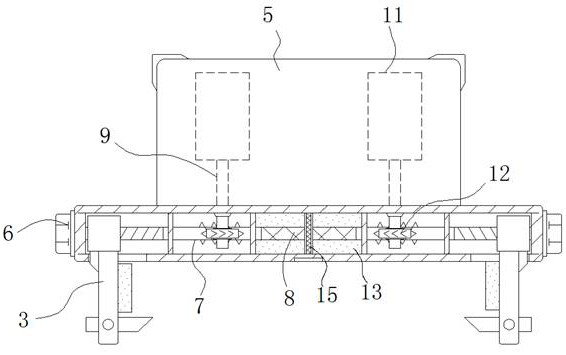
[0047] see Figure 1-7 , the present invention provides a technical solution: a prefabricated building steel structure overlapping member, comprising:

[0048] like Figure 1-2 and Figure 6-7 The technical scheme shown, the I-shaped steel 1, is provided with a positioning plate 2 between the adjacent outer walls of the overlap, and the left and right sides of the bottom of the positioning plate 2 are movably installed with side baffles 3, and the side baffles 3 The lower end is hinged with the limit hook 4, the bottom limit member of the I-shaped steel 1 at the connection between the side baffle 3 and the limit hook 4, is installed and fixed with the edge plate 5 on the top front and rear sides of the positioning plate 2, through the side baffle 3 and the movement of the limit hook 4 to laterally press and fix the lower side of the I-shaped steel, and when the side baffle 3 moves its upper structure and squeezes the side of the I-shaped steel, it can also drive the limit ho...

Embodiment 2

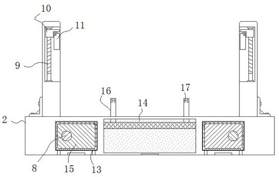
[0055] see Figure 1-5 and Figure 8-9 , the present invention provides a technical solution: a prefabricated building steel structure overlapping member, comprising:

[0056] like Figure 1-2 and Figure 8-9 The technical scheme shown, the I-shaped steel 1, is provided with a positioning plate 2 between the adjacent outer walls of the overlap, and the left and right sides of the bottom of the positioning plate 2 are movably installed with side baffles 3, and the side baffles 3 The lower end is hinged with the limit hook 4, the bottom limit member of the I-shaped steel 1 at the connection between the side baffle 3 and the limit hook 4, is installed and fixed with the edge plate 5 on the top front and rear sides of the positioning plate 2, through the side baffle 3 and the movement of the limit hook 4 to laterally press and fix the lower side of the I-shaped steel, and when the side baffle 3 moves its upper structure and squeezes the side of the I-shaped steel, it can also d...


PUM


Abstract

The invention discloses a fabricated building steel structure lap joint component which comprises I-shaped steel, a positioning plate is arranged between the adjacent lap joint outer walls of the I-shaped steel, side baffles are movably installed on the left side and the right side of the bottom of the positioning plate, limiting hooks are hinged to the lower ends of the side baffles, and limiting components are arranged at the bottoms of the I-shaped steel at the joints of the side baffles and the limiting hooks; the rotating rod pieces are rotationally installed on the front side and the rear side of the interior of the positioning plate piece, and the rotating rod pieces are in threaded connection with the side baffles; the vertical lead screw is rotationally installed on the inner side of the edge plate in an embedded mode, and a positioning sleeve is installed on the outer wall of the vertical lead screw in a threaded mode; the first liquid cavity and the second liquid cavity are sequentially formed in the positioning plate from the edge to the middle. According to the assembly type building steel structure lap joint component, stable connection between steel structure I-shaped steel is facilitated through the lap joint component, the lap joint efficiency is improved, and follow-up position adjustment and disassembly of the I-shaped steel can be facilitated.

Description

technical field [0001] The invention relates to the technical field of prefabricated buildings, in particular to a steel structure overlapping member of prefabricated buildings. Background technique [0002] Prefabricated buildings are a type of building that is different from poured concrete buildings. Through the prefabrication of walls, slabs, structural columns and other structures required for the building, the prefabricated components are directly combined and matched during the construction of the house. To generate the required house buildings, in the actual use of prefabricated buildings, the amount of assembly and construction of steel structures is much larger than that of concrete prefabricated parts. [0003] However, the existing prefabricated building steel structures have the following problems in use: [0004] When connecting and positioning steel structural columns and I-beams, the stable effect of lap joint is often achieved by angle steel and bolt connec...

Claims


Application Information

Patent Timeline
Patent Type & Authority Applications(China)
IPC IPC(8): E04B1/24E04B1/58
CPCE04B1/2403E04B1/5812E04B2001/2406
Inventor 曾顺义
Owner 曾顺义
Why Eureka
Try Eureka