Straightening device based on metal bent wire machining

A technology for bending and wire rods, applied in the field of straightening devices, can solve the problems of wire rods falling off, poor straightening effect, and easy to bend, etc., and achieve the effects of easy use, good straightening effect, and enhanced fixing effect

Inactive Publication Date: 2022-05-27
徐州百惠模具制造有限公司
View PDF0 Cites 0 Cited by
  • Summary
  • Abstract
  • Description
  • Claims
  • Application Information

AI Technical Summary

Problems solved by technology

[0004] In order to solve the above technical problems, the present invention provides a straightening device based on metal bending wire processing, to solve the problem that when straightening the wire, since the surface of the metal wire is relatively smooth, it is easy to pull the wire from slipping when pulling, As a result, the straightening effect is poor, and there is a lack of follow-up strengthening and fixing structure. At the same time, after the wire is straightened, the local small position is prone to bending, and there is a lack of auxiliary correction structure.

Method used


Image

  • Straightening device based on metal bent wire machining
  • Straightening device based on metal bent wire machining
  • Straightening device based on metal bent wire machining

Examples


Embodiment 1

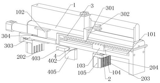
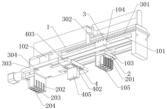
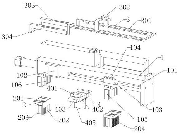
[0029] Example 1: as attached figure 1 to the attached Figure 10Shown: The present invention provides a straightening device based on metal bending wire processing, including a main body 1; the main body 1 is an L-shaped structure, and an electric push rod is installed inside the left end of the main body 1, which is used to generate power to push the moving part 103 , so that the moving piece 103 can drive the bottom piece 105 at the right end to displace together, so that the bottom piece 105 at the right end drives the wire to straighten, and a battery is provided above the left end of the main body 1, which is used to provide power for the electric push rod. The main body 1 There is a handle above the right end of the main body, so that the device can easily control the displacement, the volume is more compact, and it is more convenient to use. There are L-shaped grooves on both sides of the bottom of the main body 1, which are used to embed the ejector rod 401, so that t...

Embodiment 2

[0034] Embodiment 2: When the hardness of the straightened wire rod is relatively high, and the wire rod can be straightened at one time, it is not necessary to install the sliding member 4, so that the device can complete the straightening operation at one time, and at the same time, the work efficiency can be improved.

Embodiment 3

[0035] Embodiment 3: When encountering a thicker wire or when both ends of the wire are greatly bent, the wire can be directly embedded into the clamping plate 203, so that the wire can be directly contacted and fixed with the clamping block 202, so that the device can be used more easily. Convenient.

[0036] When using: When the device needs to be used, the device can be moved manually by using the handle, and then the position of the moving part 103 can be adjusted according to the length of the wire, and then the wire that needs to be straightened is embedded between the splints 203. A plurality of metal wires are placed, so that the device can straighten a plurality of wires. After the wires are embedded, they can contact the clamping block 202 first, so that the clamping block 202 can initially fix it, and then control the moving rod 3 to move down , so that the block 301 can be inserted into the rectangular groove of the connecting plate 104, and then connected with the...


PUM


Abstract

The invention provides a straightening device based on metal bent wire machining, relates to the field of wire machining, and aims to solve the problems that when a wire is straightened, due to the fact that the surface of the metal wire is smooth, the wire is likely to be pulled to be separated and slide down in the pulling process, and the straightening effect is poor due to lack of a follow-up reinforcing and fixing structure. The straightening device comprises a fixing part, a rectangular groove is formed in the top end of the fixing part, the fixing part comprises a clamping plate, the middle position of the clamping plate is of an inclined structure, the clamping plate is fixed to the rectangular groove of the fixing part, and the clamping plate is inserted between the inner plates through the two sides of the outer portion of the groove. During use, a metal wire is embedded between the clamping plates, so that the wire is preliminarily contacted and fixed with the clamping blocks, the moving piece receives power displacement of the electric push rod, then the fixing piece is driven by the clamping blocks to move together, and after the fixing piece moves, the clamping plates deform, the fixing blocks are contacted with the wire, and the clamping plates push the fixing blocks to clamp and fix; therefore, the device achieves the effect of follow-up reinforced fixation.

Description

technical field [0001] The invention belongs to the technical field of wire processing, and more particularly, particularly relates to a straightening device based on metal bending wire processing. Background technique [0002] When the metal wire is processed, it is usually necessary to straighten the bent metal wire, so that the bent metal wire is straightened, so as to facilitate the use of the wire, and a wire straightening device is required when the metal wire is straightened; [0003] However, when the existing wire straightening device straightens the wire, the surface of the metal wire is relatively smooth, so when pulling, the wire is easily pulled and slipped, resulting in poor straightening effect, and lack of follow-up strengthening and fixing structure. At the same time, after the wire is straightened, the local small position is prone to bending, and the structure of auxiliary correction is lacking. SUMMARY OF THE INVENTION [0004] In order to solve the ab...

Claims


Application Information

Patent Timeline
IPC IPC(8): B21F1/02
CPCB21F1/02
Inventor 刘飞
Owner 徐州百惠模具制造有限公司
Why Eureka
Try Eureka