
Sampling device for fog drop spectrometer

A sampling device and spectrometer technology, which is applied in the field of sampling devices of droplet spectrometers, can solve the problems of differences in microphysical characteristic parameters and inability to fully reflect specific locations, and achieve the effects of compact structure, prevention of condensation, and reduction of losses

Pending Publication Date: 2022-05-24
HEFEI INSTITUTES OF PHYSICAL SCIENCE - CHINESE ACAD OF SCI +2
View PDF8 Cites 0 Cited by
  • Summary
  • Abstract
  • Description
  • Claims
  • Application Information

AI Technical Summary

Problems solved by technology

[0005] Most of the current droplet spectrometers use air duct sampling. This sampling method is to sample the fixed height of the air duct connected to the droplet spectrometer and the air in a small area around the air duct at this height. However, the fog The local characteristics of the radiation fog are very obvious, especially the thickness of the radiation fog near the ground is different at different heights at the same position and at different positions at the same height, so the corresponding microphysical characteristic parameters will also be different
The current air duct sampling method reflects the average condition within a certain range and cannot fully reflect the real fog situation in a specific location. For example, in a specific road section in land traffic, there will be local heavy fog. Local characteristics require fine sampling and detection of fog in local areas to help meteorological departments provide more accurate, targeted and humanized forecast services for land traffic

Method used


Image

  • Sampling device for fog drop spectrometer
  • Sampling device for fog drop spectrometer
  • Sampling device for fog drop spectrometer

Examples


Embodiment Construction

[0027] In order to make the above-described objects, features and advantages of the present invention can be more obvious and understandable, the following in conjunction with the accompanying drawings of the specific embodiments of the present invention to make a detailed description. Many specific details are described in the following description in order to facilitate a full understanding of the present invention. However, the present invention can be implemented in many other ways different from those described herein, those skilled in the art may make similar improvements without violating the connotation of the present invention, so the present invention is not subject to the specific embodiments disclosed below.

[0028] To be clear, when a component is said to be "fixed" to another component, it can be directly on another component or it can also be present in the center. When one component is considered to be "connected" to another component, it can be directly connected ...


PUM


Abstract

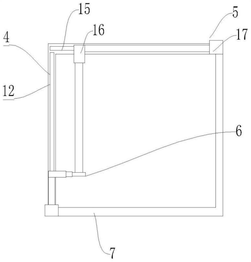
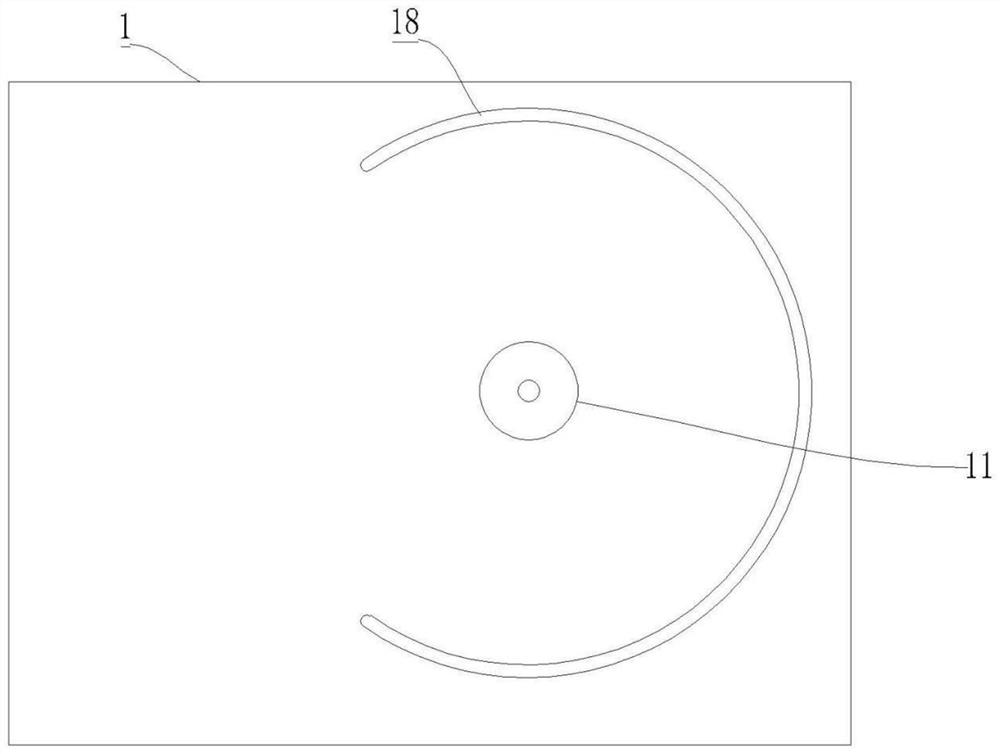
The invention provides a sampling device for a fogdrop spectrometer, the fogdrop spectrometer is arranged on a bottom plate, the bottom plate is provided with an air pump and a temperature controller, the output end of the air pump is connected with the air inlet end of the fogdrop spectrometer, a driving assembly is arranged in the bottom plate, a fixing frame is arranged on the bottom plate, the temperature controller is arranged in the fixing frame, and the fogdrop spectrometer is arranged on the bottom plate. One end of the fixing frame is connected with the driving assembly, the other end of the fixing frame is movably clamped in the bottom plate, the vertical adjusting assembly is arranged on the side wall of the fixing frame, the transverse adjusting assembly is arranged on the upper wall of the fixing frame, and the fixing ring is arranged on the transverse adjusting assembly and the vertical adjusting assembly. One end of the folding pipe is connected with an air inlet of the air pump, and the other end of the folding pipe is movably arranged on the fixing ring. According to the invention, the sampling piece is controlled to rotate and stretch out and draw back, so that radiation fog at different positions at the same height is sampled, and a more targeted forecasting service is provided for a specific road section in land traffic in a heavy fog weather local area.

Description

Technical field [0001] The present invention relates to the technical field of droplet spectrometer, in particular to a sampling apparatus for a droplet spectrometer. Background [0002] Fog is a natural weather phenomenon, it is composed of a large number of particle size in 2 ~ 100 μm of small water droplets or ice crystals composed of aerosol system, according to the formation conditions of fog can be divided into radiation fog, advection fog, mixed fog, uphill fog and front fog, fog is mostly at night to morning, after the sun will gradually dissipate, the daily change characteristics are obvious, radiation fog is particularly obvious. Radiation fog refers to the fog formed by the condensation of water vapor in the ground gas layer due to the cooling effect of radiation on the surface, which is the most common fog on the land of Our country, and it is also the most common fog in winter, which mainly appears near the ground at night or in the morning. The thickness of the radi...

Claims


Application Information

Patent Timeline
IPC IPC(8): G01N1/24G01N1/14
CPCG01N1/24G01N1/14Y02A90/10
Inventor 桂华侨孙联四琚书存程寅余同柱徐祥
Owner HEFEI INSTITUTES OF PHYSICAL SCIENCE - CHINESE ACAD OF SCI
Learn More